background image

OLIMEX© 2019

A64-OLinuXino quick start

1.2.3.

 Download the archive with the latest official image from the board's web-page to your computer. 

Extract the archive and download the image to the microSD card via the microSD card reader/writer. Make 
sure to back-up any files located on the microSD card since download the image to it, would destroy any 
data. There are a lot of software tools that can be used for downloading the image to the card. If you have no
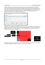
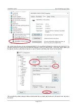
experience under Windows use “Win32 Disk Imager” tool – point to the image and select the drive 
associated with the card, then click Write. Refer to the picture:

1.2.4.

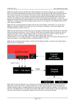
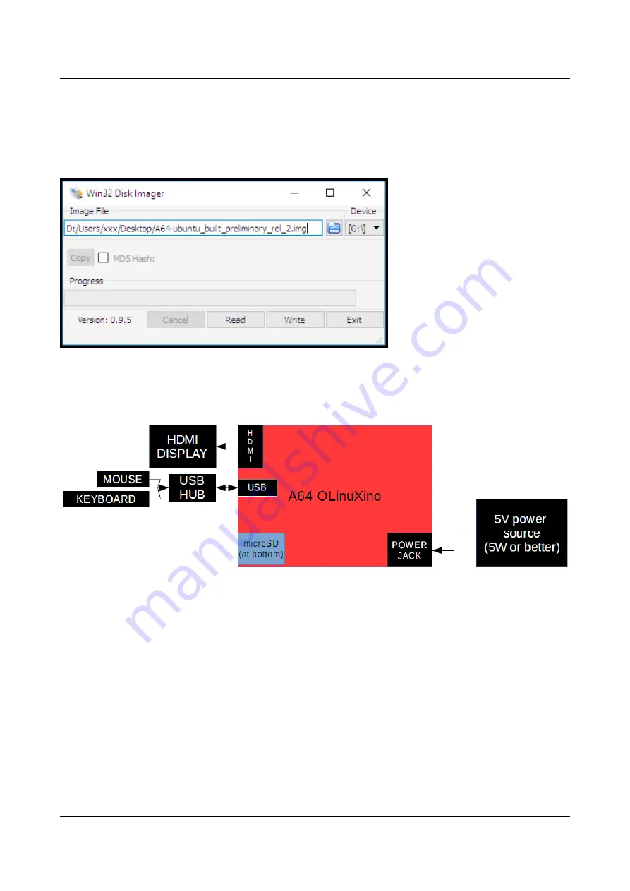
 Connect the input and output peripherals to the board. Insert the microSD card. Connect display to the

HDMI of the board. Connect the keyboard and the mouse to the USB ports. Connect LAN cable if you have 
available. Do not connect the power supply until rest of the hardware had been already connected. The 
general layout that we aim for is listed below:

1.2.5

 Power the display and apply the power supply to the board. The graphical user interface should start 

automatically. By default the super user name is “root” the password is “olimex”.

Page 4 of 9

Summary of Contents for A64-OLinuXino

Page 1: ...64 OLinuXino 64 bit open source embedded computer QUICK START GUIDE Document revision C February 2019 Designed and manufactured by OLIMEX Ltd 2017 All boards manufactured by OLIMEX LTD are RoHS compliant ...

Page 2: ...oard DC barrel jack is center positive and the inner pin is 2 0mm thick The outer hole diameter is 6 3mm The corresponding power supply plug or female jack that fits the DC barrel jack has 2 1mm inner diameter and 5 5mm outer diameter The length of the male plug should be between 10mm and 14mm For basic operation consider the 5V power adapters that we distribute SY0605E and SY0605E CHINA note that...

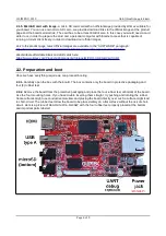
Page 3: ...ouse hardware that uses only one USB host port or specific adapter cable to fit the USB micro connector or an external USB hub USB splitter 1 2 Preparation and boot Once we have everything required we can proceed booting 1 2 1 Carefully open the box with the board The box contains only the board in protective packaging and four 4 rubber feet 1 2 2 Remove the board from the protective packaging and...

Page 4: ...s use Win32 Disk Imager tool point to the image and select the drive associated with the card then click Write Refer to the picture 1 2 4 Connect the input and output peripherals to the board Insert the microSD card Connect display to the HDMI of the board Connect the keyboard and the mouse to the USB ports Connect LAN cable if you have available Do not connect the power supply until rest of the h...

Page 5: ...hed to the LIPO_BAT1 connector there is a step up convertor to 5V so the USB ports would still work albeit the output current available would be limited For people that want to embed the board in their own designs and find using power jack PWR1 inconvenient please use the pad of FUSE2 to provide power supply and any on board GND wire or pad good places for GND are pad 2 from UEXT1 or pad 2 from GP...

Page 6: ... We distribute affordable blank microSD cards here https www olimex com Products Components Storage MICRO SD 8GB CLASS10 2 2 Preparation and boot Once we have everything require we can proceed booting 2 2 1 Carefully open the box with the board The box contains only the board in protective packaging and four 4 rubber feet 2 2 2 Remove the board from the protective packaging and place the four rubb...

Page 7: ... it 2 2 5 Connect the USB serial cable between your computer and the board At the board s side use the three male pins behind the power jack this is called the UART debug connector Refer to the picture with the layout of the board on where UART debug is located Connect cable s RX to the TX of the connector cable s RX to the TX of the connector GND of the cable ot GND of the connector Install the d...

Page 8: ...e PuTTY on the same serial port Start your serial terminal software PuTTy is shown below select the proper COM port the speed make sure that the connection is set to Serial and finally click Open at the bottom This would bring a black empty window which would be our command interface to the board once we power the board Page 8 of 9 ...

Page 9: ...rt boot data information from the board and eventually we would be requested to provide super user credentials The user name is root and the password is olimex If nothing shows up in the terminal quite likely RX and TX lines of the cable are swapped Try to change RX and TX Refer to the pictures and diagrams further up in this document Page 9 of 9 ...

Reviews: