OLIMEX© 2018
STM32-H407 user's manual
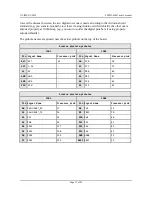
rows is the distance between the two digital rows one is made according to the Arduino shield
standard (e.g. you want to mount the row there if using Arduino certified shield), the other one is
adjusted properly at 100mil step (e.g. you want to solder the digital pins here if using properly
adjusted shields).
The pinhole names are printed near the actual pinhole on the top of the board.
Arduino platform pinholes
CON1
CON2
Pin Signal Name
Processor pin# Pin Signal Name
Processor pin#
RST
RST
25
A0
PC0
26
3V3
3.3V
-
A1
PC1
27
5V
5V
-
A2
PB0
46
GND
GND
-
A3
PB1
47
GND
GND
-
A4
PC4
44
VIN
VIN
-
A5
PC5
45
Arduino platform pinholes
CON3
CON4
Pin Signal Name
Processor pin#
Pin Signal Name
Processor pin#
D0
PA3/USART_RX
37
D8
PA1
35
D1
PA2/USART_TX
36
D9
PB11
70
D2
PG7
92
D10
PA4
40
D3
PG8
93
D11
PA7
43
D4
PG12
127
D12
PA6
42
D5
PG13
128
D13
PA5
41
D6
PG14
129
GND
AGND
31
D7
PG15
132
AREF
AREF
32
Page 17 of 30


