CONNECTOR DESCRIPTIONS
JTAG
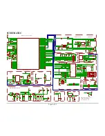
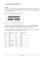
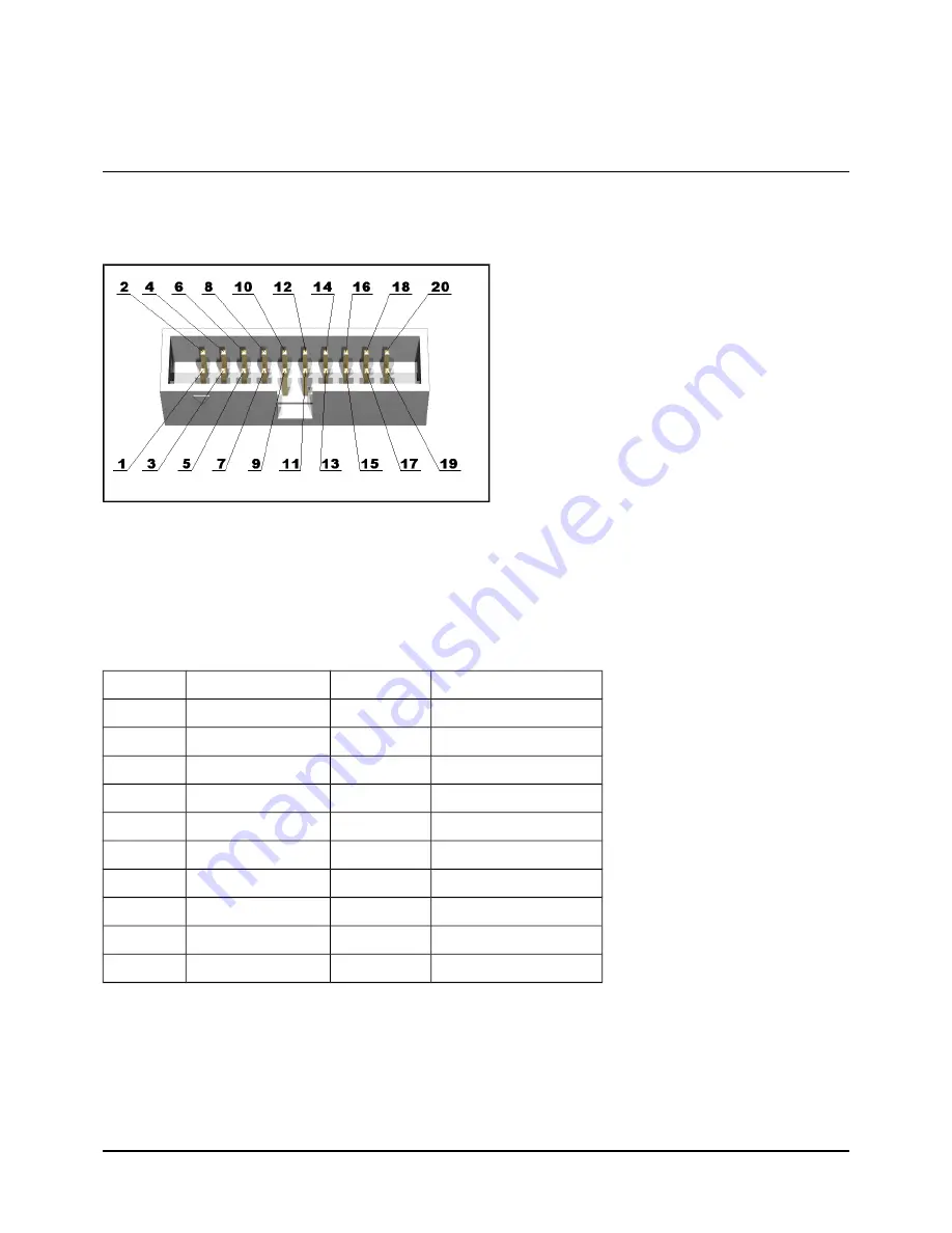
The JTAG connector is used to program and debug the board via a third-party tool. It can be used for
JTAG and SWD programming and debugging. It is recommended to use with tools that have a compatible
20-pin 0.1 step connector.
The JTAG connector allows the software debugger to talk via a JTAG (Joint Test Action Group) port
directly to the core. Instructions may be inserted and executed by the core thus allowing STM32F107
memory to be programmed with code and executed step by step by the host software.
For more details please refer to IEEE Standard 1149.1 – 1990 Standard Test Access Port and Boundary
Scan Architecture and STM32F107's datasheet and user's manual.
Pin #
Signal name
Pin #
Signal name
1
3.3V
2
3.3V
3
TRST
4
GND
5
TDI
6
GND
7
TMS
8
GND
9
TCK
10
GND
11
PULL-DOWN
12
GND
13
TDO
14
GND
15
RST
16
GND
17
PULL-DOWN
18
GND
19
+5V_JTAG
20
GND
Page 12 of 23


