background image

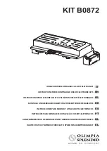
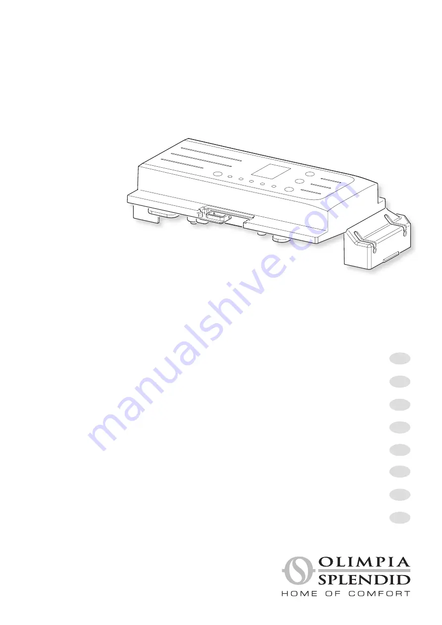
KIT B0872

NL

EL

PT

FR

EN

IT

AANWIJZINGEN VOOR DE MONTAGE EN HET GEBRUIK VAN ELEKTRONISCHE KITS

ΟΔΗΓΙΕΣ ΓΙΑ ΤΗ ΣΥΝΑΡΜΟΛΟΓΗΣΗ ΚΑΙ ΤΗ ΧΡΗΣΗ ΤΩΝ ΗΛΕΚΤΡΟΝΙΚΩΝ ΚΙΤ

INSTRUÇÕES PARA MONTAGEM E UTILIZAÇÃO DOS KITS ELETRÓNICOS

INSTRUCTIONS POUR LE MONTAGE ET L’UTILISATION DES KITS ÉLECTRONIQUES

INSTRUCTIONS FOR MOUNTING AND USE OF ELECTRONIC KITS

ISTRUZIONI PER MONTAGGIO E USO KIT ELETTRONICI

ES

DE

INSTRUCCIONES PARA MONTAR Y UTILIZAR KITS ELECTRÓNICOS

MONTAGE- UND GEBRAUCHSANLEITUNG FÜR ELEKTRONISCHE BAUSÄTZE

Summary of Contents for B0872

Page 1: ...E UTILIZA O DOS KITS ELETR NICOS INSTRUCTIONS POUR LE MONTAGE ET L UTILISATION DES KITS LECTRONIQUES INSTRUCTIONS FOR MOUNTING AND USE OF ELECTRONIC KITS ISTRUZIONI PER MONTAGGIO E USO KIT ELETTRONICI...

Page 2: ......

Page 3: ...i effettuare ogni operazione di manutenzione sull apparecchio 6 Per il corretto funzionamento dell apparecchio rispettare le distanze minime e le indicazioni riportate nel manuale di uso e manutenzion...

Page 4: ...maintenance sur l appareil 6 Pour un fonctionnement correct de l appareil respecter les distances minimales et les indications contenues dans le mode d emploi et d entretien 1 Kinder ab 8 Jahren und P...

Page 5: ...spete las distancias m nimas y las indicaciones en este manual para el uso y el mantenimiento 1 O aparelho pode ser utilizado por crian as de idade n o inferior a 8 anos e por pessoas com reduzidas ca...

Page 6: ...de reiniging of het wassen van het luchtfilter mogen uitsluitend door bevoegd en bekwaam personeel worden verricht Aangeziendeventilatorconvectoren radiatorenineeninstallatieingebouwdworden moet de o...

Page 7: ......

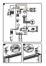
Page 8: ...L N F1 GR S2 H2 AIR M1 D1 Yc Yh 230Vac 50Hz X2 X1 X6 X8 X9 X7 X4 X3 X10 A B 1 2 1 2 1 2a 2 1 2 1 2b 1b 2a 1a 2b...

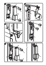
Page 9: ...3 3 3a 3 3a 3b 4 4 3 5 6 6 5 y x 6 3a 3 3b 3a 3b...

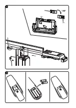
Page 10: ...180 7 7a 7b 7b 7b 7 8...

Page 11: ...I TELECOMANDO 10 3 3 USO DEL TELECOMANDO 11 3 3 a Inserimento delle batterie 11 3 3 b Sostituzione delle batterie 11 3 4 CONFIGURAZIONE DELLA SCHEDA 11 3 5 UTILIZZO DELL APPARECCHIO 14 3 5 a Accension...

Page 12: ...otrebbero derivare da uno smaltimento inadeguato del prodotto Per informazioni pi dettagliate sul riciclaggio di questo prodotto contattare l ufficio comunale il servizio locale di smaltimento rifiuti...

Page 13: ...ne della macchina in condizioni di sicurezza 0 2 a Pittogrammi redazionali Service Contrassegna situazioni nelle quali si deve informare il SERVICE aziendale interno SERVIZIO ASSISTENZA TECNICA CLIENT...

Page 14: ...a terzi senza esplicita autorizzazione della ditta OLIMPIA SPLENDID Le macchine possono subire aggiornamenti e quindi presentare particolari diversi da quelli raffigurati senza per questo costituire p...

Page 15: ...12 Installare l apparecchio secondo le istruzioni del costruttore Un errata installazione pu causare danni a persone animali o cose nei confronti dei quali il costruttore non pu essere considerato re...

Page 16: ...o di energia Evitare il contatto diretto con il flusso dell aria per un periodo prolungato Evitare che il locale rimanga chiuso a lungo Periodicamente aprire le finestre per assicurare un corretto ric...

Page 17: ...ttore ventil radiatore quindi fissarlo alla parete laterale tramite le due viti a corredo 7a fig 7 i Nel caso in cui il comando debba essere installato sul lato sinistro della macchina ripetere i pass...

Page 18: ...asi di riscaldamento la ventilazione si spegne circa 1 C prima di arrivare alla temperatura desiderata e prosegue in solo irraggiamento e convezione naturale fino alla temperatura impostata J1 OFF per...

Page 19: ...larit terminando l unit pi lontana con la resistenza da 120 Ohm fornita a corredo Abilitare la configurazione Remoto paragrafo 3 4 parametro CF configurazione Tutti i comandi saranno disabilitati e co...

Page 20: ...Trasmissione telecomando 5 Modalit Auto fan 6 Velocit ventilatore Modalit ventilatore 7 Modalit notturna 8 Accensione programmata 9 Modalit swing attiva 10 Modalit riscaldamento attiva 11 Modalit raf...

Page 21: ...ettamente le batterie a Sfilare lo sportello del vano batterie Fig 27 b Inserire le batterie nell apposito vano Fig 27 Rispettare scrupolosamente le polarit indicate sul fondo del vano batterie c Rich...

Page 22: ...0 1000 _1 Tutteleversioni 1400 1600 _2 Con flap 200 1000 Po P o s i z i o n e d i installazione Permette di selezionare dove il fancoil stato installato uP montaggio a soffitto dO montaggio a paviment...

Page 23: ...36 55 37 56 38 57 39 58 3A 59 3B 60 3C 61 3D 62 3E 63 3F 64 40 65 41 66 42 67 43 68 44 69 45 70 46 71 47 72 48 73 49 74 4A 75 4B 76 4C 77 4D 78 4E 79 4F 80 50 Co compensazione di temperature Qualora...

Page 24: ...fino all accensione alternata dei simboli blu e rosso A5 Questa impostazione viene mantenuta anche in caso di interruzione di alimentazione b Verificare successivamente che al variare della temperatu...

Page 25: ...spenti b In questa modalit operativa il ventilatore interno sempre acceso ed possibile selezionare la velocit desiderata del ventilatore in qualsiasi momento premendo l apposito tasto B6 In modalit v...

Page 26: ...alore adeguato a soddisfare la richiesta L accensione alternata dei LED rosso e blu A5 indica che attiva la modalit raffrescamento riscalda mento automatica I 4 LED e indicano la velocit di ventilazio...

Page 27: ...ella modalit corrente A5 lampeggia La funzione si attiva in raffreddamento se l unit non termostatata e se la temperatura dell acqua nella batteria superiore a 20 C da pi di 5 minuti L unit riprende i...

Page 28: ...lay del ventilconvettore mostra la scritta tI Una volta trascorso il tempo impostato l unit si avvier con le ultime impostazioni selezionate 3 13 b Settaggio timer di spegnimento dal telecomando a Con...

Page 29: ...X OFF OFF OFF ON Funzione antigelo ON AF OFF OFF OFF OFF OFF Temperatura acqua NON IDONEA in riscaldamento 18 30 ON rosso B X X X X Temperatura acqua NON IDONEA in raffreddamento 18 30 ON blu B X X X...

Page 30: ...600 800 1000 1400 1600 Descrizione Contenuto acqua batteria l 0 47 0 80 1 13 1 46 1 80 2 40 2 60 Contenuto acqua pannello radiante l 0 19 0 27 0 35 0 43 0 5 0 43 0 43 Pressione massima esercizio bar...

Page 31: ...o verso la parete Isolanti termici staccati In situazioni di elevata umidit relativa ambientale 60 si possono verificare dei fenomeni di condensa specialmente alle minime velocit di ventilazione RIMED...

Page 32: ...drenaggio nel caso pulire la bacinella e o migliorare la pendenza del tubo di drenaggio Controllare l isolamento delle tubazioni Ve r i f i c a r e l e e v e n t u a l i interferenze facendo ruotare m...

Page 33: ...EYS OF THE CONTROL PANEL 10 3 2 SYMBOLS AND KEYS OF THE REMOTE CONTROLLER 10 3 3 USE OF THE REMOTE CONTROLLER 11 3 3 a Inserting the batteries 11 3 3 b Replacing the batteries 11 3 4 BOARD CONFIGURATI...

Page 34: ...incorrect disposal Further information about the recycling of this product can be obtained from your local town hall your refuse collection service or in the store at which you bought the product Thi...

Page 35: ...of the machine in a rapid unmistakable way 0 2 a Editorial pictograms Service ReferstosituationsinwhichyoushouldinformtheSERVICEdepartmentinthecompany CUSTOMER TECHNICAL SERVICE Index Paragraphs marke...

Page 36: ...be copied or transferred to third parties without the express authorization of the manufacturer OLIMPIA SPLENDID Our machines are subject to change and some parts may appear different from the ones sh...

Page 37: ...ction 12 Install the appliance according to the instructions of the manufacturer A wrong installation may cause damages to people animals or things for which the manufacturer cannot be held liable 13...

Page 38: ...Avoid direct contact with the air flow for a prolonged period Avoid that the room remains closed for a prolonged period Periodically open the windows to ensure correct air recirculation 26 Any cleanin...

Page 39: ...e upper part of the fan coil fan radiator then secure it to the side part by means of the two supplied screws 7a fig 7 i If the control must be installed on the left side of the machine repeat the ste...

Page 40: ...ila tion In all the other cases of heating ventilation switches off approximately 1 C before reaching the desired temperature and continues in irradiation and natural convection only up to the desired...

Page 41: ...ending the farthest unit with the supplied 120 Ohm heating element Enable Remote configuration paragraph 3 4 configuration parameter CF All the commands shall be disabled and the message rE will appea...

Page 42: ...setting 2 Delay setting 3 Programmed switching off 4 Remote controller transmission 5 Auto fan mode 6 Fan speed Fan mode 7 Night mode 8 Programmed switching on 9 Swing mode active 10 Heating mode acti...

Page 43: ...e batteries To correctly insert the batteries a Remove the cover of the battery compartment Fig 27 b Insert the batteries in the specific compartment Fig 27 Scrupulously respect the polarities indicat...

Page 44: ...ll versions 1400 1600 _2 With flap 200 1000 Po Positionofinstallation Allows to select where the fancoil has been installed uP roof installation dO floor installation co Temperature compensation Allow...

Page 45: ...53 35 54 36 55 37 56 38 57 39 58 3A 59 3B 60 3C 61 3D 62 3E 63 3F 64 40 65 41 66 42 67 43 68 44 69 45 70 46 71 47 72 48 73 49 74 4A 75 4B 76 4C 77 4D 78 4E 79 4F 80 50 Co temperature compensation If...

Page 46: ...y B1 pressed for 10 seconds until the blue and red symbols A5 light up alternatively This setting is maintained also in the event of power interruption b Then ensure that when the set temperature is c...

Page 47: ...10 or cooling 11 symbols are both off b Under this operating mode the internal fan is always on and it is possible to select the desired speed of the fan at any moment by pressing the specific key B6...

Page 48: ...et the request The alternate switching on of the red and blue LEDs A5 indicates that the automatic cooling heating mode is active The 4 LEDs and indicate the set fan speed If all the 4 LEDs are off St...

Page 49: ...ve in cooling mode if the unit is not thermostatic and if water temperature in the battery is higher than 20 C from more than 5 minutes The unit immediately resumes normal operation of one of the two...

Page 50: ...e display of the fan coil shows the message tI Once the set time passes the unit will start with the last selected set tings 3 13 b Setting of the switching off timer from remote controller a With the...

Page 51: ...on ON AF OFF OFF OFF OFF OFF Water temperature NOT SUITABLE in heating mode 18 30 ON red B X X X X Water temperature NOT SUITABLE in cooling mode 18 30 ON blue B X X X X Timer ON active t I OFF OFF OF...

Page 52: ...0 Description Battery water content l 0 47 0 80 1 13 1 46 1 80 2 40 2 60 Radiant panel water content l 0 19 0 27 0 35 0 43 0 5 0 43 0 43 Maximum operating pressure bar 10 10 10 10 10 10 10 Water deliv...

Page 53: ...unit between panel and battery does not close flow towards the wall Thermal insulators are discon nected In situations of high relative am bient humidity 60 conden sation phenomenons may occur especi...

Page 54: ...in the bottom part of the battery to ensure drainage if necessary clean the basin and or improve inclination of the drain pipe Check for insulation of the pipelines Check for possible interferences by...

Page 55: ...MMANDE 10 3 2 SYMBOLES ET BOUTONS T L COMMANDE 10 3 3 UTILISATION DE LA T L COMMANDE 11 3 3 a Introduction des piles 11 3 3 b Remplacement des piles 11 3 4 CONFIGURATION DE LA CARTE 11 3 5 UTILISATION...

Page 56: ...une limination inappropri e du produit Pourdesinformationsplusd taill essurlerecyclagedeceproduit contacterlebureau municipal le service local d limination des d chets ou le magasin o le magasin a t a...

Page 57: ...de la machine en toute s curit 0 2 a Pictogrammes ditoriaux Service Il signale des situations dans lesquelles il est n cessaire d informer le SERVICE d entreprise interne SERVICE D ASSISTANCE TECHNIQ...

Page 58: ...ion de reproduction ou de transmission des tiers sans l autorisation explicite de la soci t OLIMPIA SPLENDID Les appareils peuvent subir des mises jour et par cons quent pr senter des pi ces diff rent...

Page 59: ...la terre 12 Installer l appareil selon les consignes du fabricant Une installation erron e peut causer des dommages aux personnes animaux ou choses vis vis desquels le fabricant ne peut tre tenu pour...

Page 60: ...llage d nergie inutile viter le contact direct avec le flux d air pendant une p riode prolong e viter que le local reste ferm pendant longtemps Ouvrir les fen tres p riodiquement pour assurer un bon r...

Page 61: ...duventilo convecteur ventilo radiateur puis le fixer au mur lat ral l aide de deux vis fournies 7a fig 7 i Si la commande est install e sur le c t gauche de la machine r p ter les passages du point a...

Page 62: ...les autres cas de chauffage la ventilation s teint 1 C avant d arriver la temp rature d sir e et continue uniquement en rayonnement et convection naturelle jusqu la temp rature programm e J1 OFF pour...

Page 63: ...inant l unit la plus lointaine avec la r sistance de 120 Ohm fournie Activer la configuration distance paragraphe 3 4 param tre CF configuration Toutes les commandes seront d sactiv e et la mention rE...

Page 64: ...u retard 3 Extinction programm e 4 Transmission t l commande 5 Mode Auto fan ventilateur 6 Vitesse ventilateur Mode ventilateur 7 Mode nocturne 8 Allumage programm 9 Mode swing actif 10 Mode chauffage...

Page 65: ...ectement a Retirer le cache du compartiment de la pile Fig 27 b Ins rer les piles dans le compartiment pr vu cet effet Fig 27 Respecter scrupuleusement les polarit s indiqu es sur le fond du logement...

Page 66: ...1 Toutes les versions 1400 1600 _2 Avecd flecteur 200 1000 Po Positiond installation Il permet de s lectionner la position d installation du ventilo convecteur uP montage au plafond dO Montage au sol...

Page 67: ...5 37 56 38 57 39 58 3A 59 3B 60 3C 61 3D 62 3E 63 3F 64 40 65 41 66 42 67 43 68 44 69 45 70 46 71 47 72 48 73 49 74 4A 75 4B 76 4C 77 4D 78 4E 79 4F 80 50 Co compensation de temp rature Si la particul...

Page 68: ...Cette configuration est maintenue m me en cas d interruption de l alimentation b V rifierparlasuitequelorsdelavariationdelatemp ratureprogramm el unit alternelemodeuniquement refroidissement indicate...

Page 69: ...dissement 11 soient teints b Dans ce mode op rationnel le ventilateur interne est toujours allum et il est possible de s lectionner la vitesse d sir e du ventilateur tout moment en appuyant sur le bou...

Page 70: ...demande L allumage altern des LEDS rouge ou bleu A5 indique le mode refroidissement chauffage automatique est actif Les 4 LEDS et indiquent la vitesse de ventilation configur e Si les 4 Leds sont tei...

Page 71: ...e courant A5 clignote La fonction s active en refroidissement si l unit n est pas thermostat e et si la temp rature de l eau dans la batterie est sup rieure 20 C depuis plus de 5 minutes L unit repren...

Page 72: ...he la mention tI Unefoisled laiprogramm coul l appareild marreaveclesderniers param tres s lectionn s 3 13 b R glage de la minuterie d extinction partir de la t l commande a Avec l appareil dans n imp...

Page 73: ...OFF OFF OFF Temp rature de l eau INAPPRO PRI Eenphaseder chauffement 18 30 ON rouge B X X X X Temp rature de l eau INAPPRO PRI Eenphasederefroidissement 18 30 ON bleu B X X X X Minuterie ON active t I...

Page 74: ...0 600 800 1 000 1 400 1 600 Description Contenu d eau de la batterie l 0 47 0 80 1 13 1 46 1 80 2 40 2 60 Contenu d eau du panneau radiant l 0 19 0 27 0 35 0 43 0 5 0 43 0 43 Pression maximale de serv...

Page 75: ...le flux ou vers le mur Les isolants thermiques sont d tach s Dans des situations de forte humidit ambiante 60 des ph nom nes de condensation p e u v e n t s e p r o d u i r e sp cialement aux vitesse...

Page 76: ...rifier le drainage au besoin nettoyer la bassine et ou am liorer l inclinaison du tuyau de drainage Contr ler l isolation des tuyauteries V r i f i e r l e s v e n t u e l l e s interf rences en fais...

Page 77: ...LDS 10 3 2 SYMBOLE UND TASTEN DER FERNBEDIENUNG 10 3 3 GEBRAUCH DER FERNBEDIENUNG 11 3 3 a Einsetzen der Batterien 11 3 3 b Austausch der Batterien 11 3 4 KONFIGURIERUNG DER PLATINE 11 3 5 GEBRAUCH DE...

Page 78: ...g des Produkts ergeben k nnten F r weitere Informationen zum Recycling dieses Produkts wenden Sie sich bitte an die zust ndige Gemeindestelle Ihren rtlichen Entsorgungsdienst oder an die Verkaufsstell...

Page 79: ...lichen Informationen zu liefern 0 2 a Piktogramme Service Kennzeichnet Situationen in denen der firmeneigene Kundendienst zu informieren ist TECHNISCHER KUNDENDIENST Inhaltsverzeichnis Die Abs tze den...

Page 80: ...ergabeanDritteohneausdr cklicheGenehmigung der Firma OLIMPIA SPLENDID verboten ist Die Ger te k nnen Updates unterliegen und daher Einzelteile aufweisen die von den abgebildeten abweichen ohne dass da...

Page 81: ...t gem den Anweisungen des Herstellers Eine unsachgem e Installation kann zu Verletzungen von Personen Tieren oder Gegenst nden f hren f r die der Hersteller nicht verantwortlich gemacht werden kann 1...

Page 82: ...Vermeiden den Raum l ngere Zeit geschlossen zu lassen Regelm ig die Fenster ffnen umeinenordnungsgem enLuftaustauschzugew hrleisten 26 Jegliche Reinigungsarbeit ist untersagt solange das Ger t nicht v...

Page 83: ...eferten Schrauben 7a befestigen Abb 7 i F r den Fall dass das Bedienfeld auf der linken Seite des Ger ts installiert werden soll die Schritte ab Punkt a bis Punkt i wiederholen jedoch die Halterung 7b...

Page 84: ...en F llen von Heizung schaltet die L ftung etwa 1 C vor Erreichen der gew nschten Temperatur ab und f hrt mit alleiniger Abstrahlung und nat rlichem W rme bergang bis zur eingestellten Temperatur fort...

Page 85: ...mit dem mitgelieferten Widerstand zu 120 Ohm abzuschlie en Die Konfiguration Remote Absatz 3 4 Parameter CF Konfigurierung freigeben S mtlicheBedienungen werdengesperrtundaufdemDisplayerscheintderSch...

Page 86: ...Aus 1 Einstellung der Temperatur 2 Einstellung Verz gerung 3 Programmierte Ausschaltung 4 Fernbedienungssignal 5 Betriebsart AUTO FAN L fter 6 L ftergeschwindigkeit bzw L ftermodus 7 Nachtmodus 8 Prog...

Page 87: ...a Den Deckel des Batteriefachs herausziehen Abb 27 b Die Batterien in das entsprechende Fach einsetzen Abb 27 Die auf dem Boden des Batteriefachs angezeigte Polarit t strikt befolgen c Den Batteriefa...

Page 88: ...sekonvektor _0 Ohne Klappe 200 1000 _1 Alle Ausf hrungen 1400 1600 _2 Mit Klappe 200 1000 Po Installationslage Erm glicht die Wahl wo der Gebl sekonvektor installiert wurde uP Deckenmontage dO Bodenm...

Page 89: ...38 57 39 58 3A 59 3B 60 3C 61 3D 62 3E 63 3F 64 40 65 41 66 42 67 43 68 44 69 45 70 46 71 47 72 48 73 49 74 4A 75 4B 76 4C 77 4D 78 4E 79 4F 80 50 Co Temperaturausgleich SoferndiebesondereInstallatio...

Page 90: ...bols A5 10 Sekunden lang gedr ckt halten Diese Einstellung wird auch im Fall einer Stromunterbrechung beibehalten b Anschlie end kontrollieren dass bei nderung der eingestellten Temperatur das Ger t d...

Page 91: ...Betriebsmodus ist der innere L fter immer eingeschaltet und es ist m glich die gew nschte Geschwindigkeit des L fters jederzeit durch Dr cken der entsprechenden Taste B6 zu w hlen Im L ftermodus blei...

Page 92: ...frage zu befriedigen Das abwechselndeAufleuchten der roten und blauen LED A5 zeigt an dass der automatische K hl bzw Heizmodus aktiv ist Die 4 LED und zeigen die eingestellte L ftergeschwindigkeit an...

Page 93: ...mostat angeschlossen ist und die Temperatur des Wassers in der Batterie seit mehr als 5 Minuten mehr als 20 C betr gt Das Ger t nimmt unverz glich den normalen Betrieb wieder auf wenn eine der beiden...

Page 94: ...ay des Bedienfelds am Ger t den Schriftzug tl anzeigt Nach Ablauf der eingestellten Zeit wird das Ger t mit den letzten Einstellungen gestartet 3 13 b Einstellung des Ausschalt Timers von der Fernbedi...

Page 95: ...rostschutzfunktion EIN AF AUS AUS AUS AUS AUS UNGEEIGNETE Wassertempe ratur im Heizmodus 18 30 EIN rot B X X X X UNGEEIGNETE Wassertempe ratur im K hlmodus 18 30 EIN blau B X X X X Timer EIN aktiv t I...

Page 96: ...0 1600 Beschreibung Wasserinhalt der Batterie l 0 47 0 80 1 13 1 46 1 80 2 40 2 60 Wasserinhalt der Heizplatte l 0 19 0 27 0 35 0 43 0 5 0 43 0 43 Max Betriebsdruck bar 10 10 10 10 10 10 10 Maximale W...

Page 97: ...til unterbricht den Fluss zur Platte nicht Gel stes Isoliermaterial In F llen von hoher relativer Raumluftfeuchtigkeit 60 kann es zu Kondensbildung kommen insbesondere bei den Mindest L ftergeschwindi...

Page 98: ...zu berpr fen notfalls die Schale reinigen und oder die Neigung der Drainageleitung verbessern Die Isolierung der Leitungen berpr fen Die eventuellen Ber hrungspunk te durch Drehen des L fters von Hand...

Page 99: ...Y TECLAS DEL MANDO A DISTANCIA 10 3 3 USO DEL MANDO A DISTANCIA 11 3 3 a Inserci n de las bater as 11 3 3 b Sustituci n de las bater as 11 3 4 CONFIGURACI N DE LA PLACA 11 3 5 USO DEL APARATO 14 3 5 a...

Page 100: ...e y la salud Otras informaciones sobre el reciclado de este producto las obtendr de su ayuntamiento recogida de basura o en el comercio donde haya adquirido el producto Esta norma es v lida nicamente...

Page 101: ...e seguridad 0 2 a Pictogramas informativos Servicio Indica situaciones en las cuales se debe informar al SERVICE empresarial interno SERVICIO ASISTENCIA T CNICA A CLIENTES ndice los p rrafos precedido...

Page 102: ...MPIA SPLENDID Las m quinas pueden ser actualizadas y por lo tanto presentar detalles distintos respecto a aquellos representados sin constituir por ello perjuicio para los textos contenidos en el pres...

Page 103: ...ma de corriente se debe equipar con una conexi n a tierra 12 Instale el aparato seg n las instrucciones del constructor Una instalaci n incorrecta puede causar da os a personas animales o bienes hacia...

Page 104: ...con el flujo de aire durante periodo prolongado Evite que la habitaci n se quede cerrada durante mucho tiempo Peri dicamente abra las ventanas para asegurar el correcto cambio del aire 26 Se proh be...

Page 105: ...del ventilconvector ventil radiador entonce fijarlo a la pared a trav s de los dos tornillos suministrados 7a fig 7 i En el caso de que el mando se deba instalar en el lado izquierdo de la m quina re...

Page 106: ...amiento la ventilaci n se apaga aproximadamente 1 C antes de alcanzar la temperatura deseada y continua en modo s lo irradiaci n y convecci n natural hasta la temperatura configurada J1 OFF para apara...

Page 107: ...la unidad m s lejana con la resistencia de 120 Ohm suministrada Habilite la configuraci n Remoto p rrafo 3 4 par metro CF configuraci n Todos los mandos se deshabilitan y en la pantalla aparece el me...

Page 108: ...gramado 4 Transmisi n del mando 5 Modo Auto fan 6 Velocidad ventilador Modo ventilador 7 Modo nocturno 8 Arranque programado 9 Modo swing activo 10 Modo calentamiento activo 11 Modo enfriamiento activ...

Page 109: ...a puerta del compartimiento de las bater as Fig 27 b Inserte las bater as en el compartimiento espec fico Fig 27 Respetar escrupulosamente las polaridades indicadas en el fondo del compartimiento bate...

Page 110: ...flap 200 1000 _1 Todaslasversiones 1400 1600 _2 Con flap 200 1000 Po Posici n de instalaci n Permiteseleccionardondeest instalado el ventilconvector uP montaje de techo dO montaje de pavimento co Com...

Page 111: ...37 56 38 57 39 58 3A 59 3B 60 3C 61 3D 62 3E 63 3F 64 40 65 41 66 42 67 43 68 44 69 45 70 46 71 47 72 48 73 49 74 4A 75 4B 76 4C 77 4D 78 4E 79 4F 80 50 Co compensaci n de temperaturas En el caso de q...

Page 112: ...dido alternado de los s mbolos azul y rojo A5 Esta configuraci n se mantiene tambi n en caso de interrupci n de alimentaci n b Luego verificar que al cambiar de la temperatura configurada la unidad al...

Page 113: ...iamiento 11 est n apagados b En este modo operativo el ventilador interno siempre est encendido y es posible seleccionar la velocidad deseada del ventilador en cualquier momento presionando la tecla e...

Page 114: ...icitud El encendido alternado de los LED rojo y azul A5 indica que el modo enfriamiento calentamiento auto m tico es activo Los 4 LED y indican la velocidad de ventilaci n configurada Si todos los 4 L...

Page 115: ...a funci n se activa en enfriamiento si la unidad no tiene un termostato y si la temperatura del agua en la bater a es superior a los 20 C desde m s de 5 minutos La unidad restablece inmediatamente el...

Page 116: ...tilconvector muestra el mensaje tI Una vez transcurrido el tiempo configurado la unidad se arrancar con las ltimas configuraciones seleccionadas 3 13 b Configuraci n del temporizador de apagado desde...

Page 117: ...lante ON AF OFF OFF OFF OFF OFF Temperatura agua NO ID NEA en modo calentamiento 18 30 ON rojo B X X X X Temperatura agua NO ID NEA en modo enfriamiento 18 30 ON azul B X X X X Temporizador ON activo...

Page 118: ...0 400 600 800 1000 1400 1600 Descripci n Contenido agua bater a l 0 47 0 80 1 13 1 46 1 80 2 40 2 60 Contenido agua panel radiante l 0 19 0 27 0 35 0 43 0 5 0 43 0 43 Presi n m xima de funcionamiento...

Page 119: ...pared Aislantest rmicosdesconectados En situaciones de alta hume dad relativa ambiental 60 podr an ocurrir fen menos de condensaci n especialmente a las velocidades m nimas de ventilaci n REMEDIO Espe...

Page 120: ...ecesario limpie el dep sito y o mejorar la inclinaci n del tubo de drenaje Controlar el aislamiento de los tubos Ve r i f i c a r l a s p o s i b l e s interferencias haciendo rotar manualmente el ven...

Page 121: ...MANDOS 10 3 2 S MBOLOS E TECLAS DO CONTROLO REMOTO 10 3 3 USO DO CONTROLO REMOTO 11 3 3 a Introdu o das pilhas 11 3 3 b Substitui o das pilhas 11 3 4 CONFIGURA O DA PLACA 11 3 5 USO DO APARELHO 14 3 5...

Page 122: ...uma elimina o inadequada do produto Para informa es mais pormenorizadas sobre a reciclagem deste produto entre em contacto com a reparti o municipal o servi o local de elimina o de res duos ou a loja...

Page 123: ...orreta utiliza o da m quina em condi es de seguran a 0 2 a Pictogramas editoriais Service Sinaliza situa es nas quais o SERVICE interno da empresa deve ser informado SERVI O DE ASSIST NCIA T CNICA CLI...

Page 124: ...e reprodu o ou de transmiss o a terceiros sem expl cita autoriza o da empresa OLIMPIA SPLENDID As m quinas podem sofrer atualiza es e portanto apresentar particulares diferentes daqueles mostrados sem...

Page 125: ...ser equipada com liga o terra 12 Instale o aparelho de acordo com as instru es do fabricante Uma instala o errada pode causar danos a pessoas a animais ou coisas em rela o aos quais o fabricante n o...

Page 126: ...te o contacto direto com o fluxo de ar por um per odo prolongado Evite que o local permane a fechado por muito tempo Abra periodicamente as janelas para assegurar uma correta troca de ar 26 proibida q...

Page 127: ...superior do ventiloconvector ventilorradiador e em seguida fixe o na parede lateral usando os dois parafusos fornecidos 7a fig 7 i Se o comando tiver que ser instalado no lado esquerdo da m quina repi...

Page 128: ...outros casos de aquecimento a ventila o desliga se cerca de 1 C antes de atingir a temperatura desejada e continua apenas em irradia o e convec o natural at temperatura definida J1 OFF para dispositi...

Page 129: ...rminando a unidade mais afastada com a resist ncia de 120 Ohm fornecida Habilite a configura o remota par grafo 3 4 par metro CF configura o Todos os comandos ser o desativados e a escrita rE aparecer...

Page 130: ...Desligamento programado 4 Transmiss o controlo remoto 5 Modo Auto fan 6 Velocidade ventilador Modo ventilador 7 Modo noturno 8 Acendimento programado 9 Modalidade de swing ativa 10 Modo de aquecimento...

Page 131: ...has Para inserir as pilhas corretamente a Retire a portinhola do compartimento das pilhas Fig 27 b Introduza as pilhas no compartimento das pilhas Fig 27 Observe rigorosamente as polaridades indicadas...

Page 132: ...em flap 200 1000 _1 Todas as vers es 1400 1600 _2 Com flap 200 1000 Po Posi odeinstala o Permite selecionar onde a bobina de ventila o foi instalada uP montagem no teto dO montagem no pavimento co Com...

Page 133: ...2 34 53 35 54 36 55 37 56 38 57 39 58 3A 59 3B 60 3C 61 3D 62 3E 63 3F 64 40 65 41 66 42 67 43 68 44 69 45 70 46 71 47 72 48 73 49 74 4A 75 4B 76 4C 77 4D 78 4E 79 4F 80 50 Co compensa o de temperatur...

Page 134: ...gundosat oss mbolosazulevermelhoalternarem A5 Estaconfigura o tamb m mantida em caso de interrup o de alimenta o b Posteriormente verifique se quando a temperatura ajustada muda a unidade muda apenas...

Page 135: ...ligados b Nesta modalidade operativa o ventilador interno est sempre aceso e poss vel selecionar a velocidade desejada do ventilador em qualquer momento pressionando a tecla B6 No modo de ventila o a...

Page 136: ...os LEDs vermelho e azul A5 indica que o modo de arrefecimento aquecimento autom tico est ativo Os 4 LEDs e indicam a velocidade de ventila o definida Se todos os 4 LEDs estiverem desligados o modo Sta...

Page 137: ...odo atual A5 pisca A fun o ativada no arrefecimento se a unidade n o estiver termostatizada e se a temperatura da gua na bateria tiver sido superior a 20 C durante mais de 5 minutos A unidade retoma i...

Page 138: ...or mostra a escrita tI Depois de decorrido o tempo configurado a unidade come ar com as ltimas configura es selecionadas 3 13 b Configura o do temporizador de desligamento do controlo remoto a Com a u...

Page 139: ...X OFF OFF OFF ON Fun o antigelo ON AF OFF OFF OFF OFF OFF Temperatura da gua N O ADEQUADA no aquecimento 18 30 ON verme lho B X X X X Temperatura da gua N O ADEQUADA no arrefecimento 18 30 ON azul B...

Page 140: ...0 400 600 800 1000 1400 1600 Descri o Conte do de gua da bateria l 0 47 0 80 1 13 1 46 1 80 2 40 2 60 Conte do de gua do painel radiante l 0 19 0 27 0 35 0 43 0 5 0 43 0 43 Press o m xima de funcionam...

Page 141: ...m dire o parede Isolantes t rmicos desconecta dos Em situa es de elevada humidade relativa do ambiente 60 podem se verificar fen menos de condensa o especialmente com velocidades de ventila o m nimas...

Page 142: ...drenagem caso seja necess rio limpe a bacia e ou melhorar a pend ncia do tubo de drenagem Controle o isolamento das tuba gens Verifique se existem interfer n cias girando manualmente a ventoinha O de...

Page 143: ...3 2 SYMBOLEN EN TOETSEN AFSTANDSBEDIENING 10 3 3 GEBRUIK VAN DE AFSTANDSBEDIENING 11 3 3 a De batterijen plaatsen 11 3 3 b Vervanging van de batterijen 11 3 4 CONFIGURATIE VAN DE KAART 11 3 5 GEBRUIK...

Page 144: ...een ongeschikte verwijdering van het product vermijden Informeer bij de gemeente de plaatselijke afvalverwijderingsdienst of de winkel waar het product aangeschaft is naar meer informatie over de recy...

Page 145: ...hine veilig te kunnen gebruiken 0 2 a Pictogrammen Service Geeft situaties aan waarin de interne SERVICE moet worden gewaarschuwd TECHNISCHE KLANTENDIENST Inhoudsopgave Paragrafen die van dit symbool...

Page 146: ...t een verbod op verveelvoudiging of overdracht aan derden zonder uitdrukkelijke toestemming van OLIMPIA SPLENDID De machines kunnen worden bijgewerkt en daarom andere details vertonen dan aangeduid zo...

Page 147: ...tact moet met een aarding uitgerust zijn 12 Installeer het apparaat volgens de instructies van de fabrikant Een verkeerde installatie kan persoonlijk letsel dierenleed of materi le schade veroorzaken...

Page 148: ...ijd de langdurige directe aanraking met de luchtstroom Vermijd dat de ruimte te lang gesloten blijft Open de ramen regelmatig om een correcte luchtverversing te waarborgen 26 Het is verboden om het ap...

Page 149: ...van de ventilatorconvector radiator en zet hem met de geleverde twee schroeven 7a vast aan de muur afb 7 i Herhaal de stappen van punt a tot punt i en verplaats de steun 7b daarbij zoals is aangegeven...

Page 150: ...akelt de ventilator uit als de verwarming een temperatuur heeft bereikt die ongeveer 1 C afwijkt van de gewenste temperatuur vervolgens werkt de verwarming enkel met straling en natuurlijke convectie...

Page 151: ...volgens de aangegeven polariteit en sluit de verst geplaatste unit af met de geleverde weerstand van 120 Ohm Activeer de configuratie Remote paragraaf 3 4 configuratieparameter CF Alle bedieningen wo...

Page 152: ...grammeerde uitschakeling 4 Verzending afstandsbediening 5 Modus Auto fan 6 Ventilatorsnelheid modus ventilator 7 Modus s nachts 8 Geprogrammeerde inschakeling 9 Modus swing geactiveerd 10 Verwarmingsm...

Page 153: ...e plaatsen a Verwijder het klepje van het batterijvak Afb 27 b Breng de batterijen in het batterijvak aan Afb 27 Houd u nauwgezet aan de polariteit die op de bodem van het batterijvak is aangegeven c...

Page 154: ...fancoil _0 Zonder flap 200 1000 _1 Alle versies 1400 1600 _2 Met flap 200 1000 Po Installatiepositie Voor de selectie van de plaats waar de fancoil ge nstalleerd is uP montage aan het plafond dO mont...

Page 155: ...37 56 38 57 39 58 3A 59 3B 60 3C 61 3D 62 3E 63 3F 64 40 65 41 66 42 67 43 68 44 69 45 70 46 71 47 72 48 73 49 74 4A 75 4B 76 4C 77 4D 78 4E 79 4F 80 50 Co temperatuurcompensatie Als de installatie va...

Page 156: ...drukt te houden tot de blauwe en rode symbolen A5 afwisselend worden weergegeven Deze instelling blijft behouden ook bij een stroomstoring b Controleer vervolgens of de unit de modus alleen koelen bla...

Page 157: ...nden b In deze modus is de interne ventilator altijd ingeschakeld en kan op elk gewenst moment de gewenste ventilatorsnelheid worden geselecteerd met een druk op de specifieke toets B6 In de modus ven...

Page 158: ...aag voldoet Alsderodeenblauweleds A5 afwisselendknipperen houdtditindatdeautomatischekoeling verwarming is geactiveerd De 4 leds en geven de ingestelde ventilatiesnelheid aan De modus stand by is geac...

Page 159: ...unit niet over een thermostaat beschikt en de temperatuur van het water in de warmtewisselaar meer dan 5 minuten lang hoger is dan 20 C Als een van deze voorwaarden niet aanwezig is hervat de unit on...

Page 160: ...atorconvector tI weergegeven wordt Na verloop van de ingestelde tijd zal de unit starten met de laatst gekozen instellingen 3 13 b Instelling uitschakeltimer met afstandsbediening a Druk met de unit i...

Page 161: ...Antivriesfunctie ON AF OFF OFF OFF OFF OFF Watertemperatuur NIET GESCHIKT tijdens verwarmen 18 30 ON rood B X X X X Watertemperatuur NIET GESCHIKT tijdens koelen 18 30 ON blauw B X X X X Timer ON gea...

Page 162: ...0 1400 1600 Beschrijving Hoeveelheid water warmtewisselaar l 0 47 0 80 1 13 1 46 1 80 2 40 2 60 Hoeveelheid water stralingspaneel l 0 19 0 27 0 35 0 43 0 5 0 43 0 43 Maximale bedrijfsdruk bar 10 10 10...

Page 163: ...eekt de stroming naar de muur niet Thermisch isolatiemateriaal losgeraakt B i j e e n h o g e r e l a t i e v e luchtvochtigheid 60 kan condens ontstaan met name bij lage ventilatiesnelheden OPLOSSING...

Page 164: ...en Maak het reservoir eventueel schoon en of laat de afvoerleiding meer hellen Controleer de isolatie van de leidingen Laat de ventilator met de hand draaien en controleer of deze niets raakt Een verk...

Page 165: ...1 3 7 2 7 2 1 8 2 2 9 2 3 B0736 MODBUS 9 2 4 SIOS CONTROL 9 3 10 3 1 10 3 2 10 3 3 11 3 3 a 11 3 3 b 11 3 4 11 3 5 14 3 5 a 14 3 6 14 3 7 14 3 8 15 3 8 a 15 3 8 b 15 3 9 16 3 10 LED 16 3 11 SWING 16...

Page 166: ...EL 2 3 13 TIMER 18 3 13 a timer 18 3 13 b timer 18 3 14 18 3 15 LED 19 3 16 20 4 20 5 21...

Page 167: ...KIT B0872 EL 3 0 0 1 0 2 0 2 a...

Page 168: ...EL 4 0 3 1 OLIMPIA SPLENDID 2 3 4 5 6...

Page 169: ...KIT B0872 EL 5 7 8 9 OLIMPIA SPLENDID 10 11 12 13 A 14 15 16 17 18 19...

Page 170: ...EL 6 20 OLIMPIA SLPENDID 21 22 23 24 25 26 27 28 29 70 C 30 OLIMPIA SPLENDID 2014 35 EU 2014 30 EU RoHS 2011 65 CE...

Page 171: ...KIT B0872 EL 7 2 1 1 1 2 2a 2b a 1a 1b b 1 c 2a 2b d 2 1 3 a 3a 3 b 3b 3 3 c 4 5 4 d 3 6 4 e x y 4 N 5 f g 3b 3 3a 6 h 7 7a 7 i a i 7b 7 2 3G 0 75 20 mm 30 mA...

Page 172: ...Yc 230V 50Hz max 10W Gr F1 L N S2 A Modbus B Modbus D1 2 1 J1 J2 e J3 1 J1 ON 1 C J1 OFF J2 ON J2 OFF J3 ON 2 Yc J3 OFF 4 Yc Yh 5 D1 C0 C1 C2 C3 C4 C5 C6 C7 J1 OFF OFF OFF OFF ON ON ON ON J2 OFF OFF O...

Page 173: ...B 1 Economy X8 2x0 5 mm2 20 m 2 3 B0736 MODBUS X8 X7 B0736 AB B0736 AB 120 Ohm 3 4 CF rE B0736 2 4 SIOS CONTROL X8 X7 A B SIOS CONTROL A B 120 Ohm 3 4 CF ASCII SIOS CONTROL B0863 RTU SIOS CONTROL B08...

Page 174: ...h 3 8 7 6 5 9 4 2 11 10 1 B1 B9 B8 B5 B2 B6 B3 B11 B4 B10 B7 T3 A5 A4 A3 A2 A1 T2 T1 B EL 10 3 3 1 B B1 ON Standby B2 B3 B4 B5 B6 max med min auto B7 LED B8 B9 B10 B11 on off 1 2 3 4 5 Auto fan 6 7 8...

Page 175: ...KIT B0872 EL 11 3 3 TV 3 3 a 27 27 27 3 3 b 1 5V AAA 27 3 4 stand by T2 T1 5 T1 T1 CF bU Ad Fa Po co CF T2 T2 3...

Page 176: ...Fa Fancoil fancoil _0 200 1000 _1 1400 1600 _2 200 1000 Po fancoil uP dO co 5 5 bU BUS Modicon Modbus ASCII Modicon Modbus RTU Baudrate 9600 Baudrate 9600 data bits 7 data bits 8 stop bit 1 stop bit...

Page 177: ...0 1E 31 1F 32 20 33 21 34 22 35 23 36 24 37 25 38 26 39 27 40 28 41 29 42 2A 43 2B 44 2C 45 2D 46 2E 47 2F 48 30 49 31 50 32 51 33 52 34 53 35 54 36 55 37 56 38 57 39 58 3A 59 3B 60 3C 61 3D 62 3E 63...

Page 178: ...EL 14 3 5 3 5 a T2 2 B1 stand by 5 C AF 3 6 B1 10 A5 A5 A5 B1 2 LED LED LED LED 3 7 3 10 A5 3 2 LED LED LED LED B2 10 11...

Page 179: ...KIT B0872 EL 15 3 8 3 2 LED LED LED LED T2 B2 10 11 B6 3 8 a T2 A4 B6 6 3 8 b T2 A3 B6 5...

Page 180: ...EL 16 3 9 T2 A1 T2 B11 7 B11 1 C 2 1 C 2 J1 ON 3 10 LED LED A5 LED A5 4 LED 4 Led Stand by LED soft blinking LED 5 LED 15 7 led 15 LED 15 3 11 SWING B3 9 B3 9...

Page 181: ...KIT B0872 EL 17 3 12 3 12 a Air sampling 1 3 12 b T1 5 BL 3 12 c 5 20 C 5 30 C 30 C 30 3 12 d X4 E3 10 T2 T3 3 12 e 180 5 T1 T3...

Page 182: ...6 0 H 0 h 6 0 H 3 0 H 0 h 3 0 H EL 18 3 13 TIMER 3 13 a timer B8 1 24 5 tl 3 13 b timer 9 1 24 5 tl 3 14...

Page 183: ...18 30 OFF X X X X X X ON OFF OFF OFF X X OFF ON OFF OFF X X OFF OFF ON OFF X X OFF OFF OFF ON AF OFF OFF OFF OFF OFF 18 30 ON B X X X X 18 30 ON B X X X X Timer ON t I OFF OFF OFF OFF OFF Timer OFF t...

Page 184: ...200 400 600 800 1000 1400 1600 l 0 47 0 80 1 13 1 46 1 80 2 40 2 60 l 0 19 0 27 0 35 0 43 0 5 0 43 0 43 bar 10 10 10 10 10 10 10 C 80 80 80 80 80 80 80 C 4 4 4 4 4 4 4 Eurokonus 3 4 Eurokonus 3 4 Eur...

Page 185: ...KIT B0872 EL 21 5 60 2 3 silent 220 V...

Page 186: ...EL 22 FI E2 E3 E4 E5 stand by 5 T2 T3...

Page 187: ......

Page 188: ...263995A...

Reviews: