ENGLISH
EN - 8
Connection to the mains supply can be carried out with fixed connection or with mobile plug and
MUST be equipped with an omnipolar switch compliant with the current IEC EN standards, with
a contact opening of at least 3mm (better if equipped with fuses).
Correct connection to the ground system is essential to ensure safety of the
appliance.
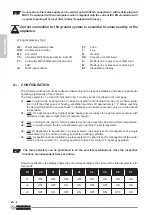
Wiring diagram key (fig.1)
H2:
Water temperature probe
AIR:
Air temperature probe
M1:
Fan motor
Yh:
Hot water 230V-50Hz solenoid valve, max 10W
Yc:
Cold water 230V-50Hz solenoid valve, max
10W
Gr
: Grille input contact
F1:
Fuse
L:
Line
N:
Neutral
S2:
Presence contact input
A:
Modbus line or presence contact input
B:
Modbus line or presence contact input
D1:
Visualization display
2.1 - CONFIGURATION
The printed circuit board must be configured depending on the type of installation and based on particular
operating preferences of the machine.
The three selectors J1, J2 and J3 indicated in fig. 1 must be set as described in the next page:
J1.
ON: in night mode, heating works in natural convection and irradiation mode only, without ventila-
tion; In all the other cases of heating, ventilation switches off approximately 1°C before reaching
the desired temperature and continues in irradiation and natural convection only up to the desired
temperature.
J1.
OFF: for appliances without radiant panel: heating occurs always through forced convection, with
activation active also in night mode (at reduced speed).
J2.
ON: in cooling mode, the fan remains powered even upon reach the desired ambient temperature.
J2.
OFF: in cooling mode, the fan id deactivated upon reaching the set temperature.
J3.
ON: for appliances to be installed in 2-pipes systems: the board is set for management of a single
water valve (Yc) for summer (cooling) and winter (heating) operation.
J3.
OFF: for appliances to be installed in 4-pipes systems: the board is set for management of two water
valves, one for summer (Yc - cooling) operation and one for winter (Yh -heating) operation.
The three selectors can be positioned in all the possible combinations since the respective
functions are independent from each other.
At each reactivation, the display shows the code corresponding to the setting of the internal selectors for
5 seconds:
D1
C0
C1
C2
C3
C4
C5
C6
C7
J1
OFF
OFF
OFF
OFF
ON
ON
ON
ON
J2
OFF
OFF
ON
ON
OFF
OFF
ON
ON
J3
OFF
ON
OFF
ON
OFF
ON
OFF
ON
Summary of Contents for B0872
Page 2: ......
Page 7: ......
Page 9: ...3 3 3a 3 3a 3b 4 4 3 5 6 6 5 y x 6 3a 3 3b 3a 3b...
Page 10: ...180 7 7a 7b 7b 7b 7 8...
Page 166: ...EL 2 3 13 TIMER 18 3 13 a timer 18 3 13 b timer 18 3 14 18 3 15 LED 19 3 16 20 4 20 5 21...
Page 167: ...KIT B0872 EL 3 0 0 1 0 2 0 2 a...
Page 168: ...EL 4 0 3 1 OLIMPIA SPLENDID 2 3 4 5 6...
Page 169: ...KIT B0872 EL 5 7 8 9 OLIMPIA SPLENDID 10 11 12 13 A 14 15 16 17 18 19...
Page 179: ...KIT B0872 EL 15 3 8 3 2 LED LED LED LED T2 B2 10 11 B6 3 8 a T2 A4 B6 6 3 8 b T2 A3 B6 5...
Page 185: ...KIT B0872 EL 21 5 60 2 3 silent 220 V...
Page 186: ...EL 22 FI E2 E3 E4 E5 stand by 5 T2 T3...
Page 187: ......
Page 188: ...263995A...


