KIT B0872
ENGLISH
EN - 9
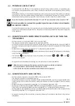
2.2 - PRESENCE CONTACT INPUT
To terminals “
A”
and “
B”
(fig. 1) it is possible to connect a free contact, not live, of a possible pres
-
ence sensor (not supplied) which, when closed, causes the deactivation of the appliance (factory setting
stand-by).
It is possible, in factory or an authorized assistance centre upon prior request of the customer, to change
this function so that the selected ambient temperature is automatically increased (in cooling mode) or
decreased (in heating mode) by a specific value “Economy Function” when the contact is closed.
To use this function, check that the terminals “A” and “B” are connected to the connector “X8”.
It is not possible to connect the parallel input the one of other circuit boards;
use separate contacts.
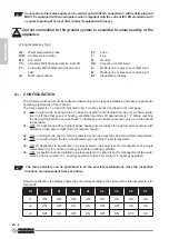
To connect the presence sensor, it is necessary to use a double-insulated cable with a minimum section
of 2x0,5 mm
2
and maximum length of 20 m. Keep this connection separated from the power supply line
of the appliance.
2.3 - CONNECTION WITH WIRED REMOTE CONTROL B0736 OR THIRD PAR-
TIES MODBUS
- Set the connector on connection
“X8”
on the connector
“X7”
.
The presence contact will be managed by the wall control B0736.
- Connect the cables coming from the connection
“A B”
of the control B0736 with the connector
“A B”
of
the control, taking care to respect the polarity, ending the farthest unit with the supplied 120 Ohm heating
element.
- Enable Remote configuration (paragraph “3.4”, configuration parameter “
CF
”).
- All the commands
“
”
shall be disabled and the message
"rE"
will appear on the display
every time they are activated.
- The indicator
“
”
shows the chosen mode of operation, the indicators
“
”, “
”, “
”
and
“
”
and the set fan speeds.
- As regards the functionalities and settings, see the instructions of command B0736.
- When the unit is configured for remote control, the remote controller is disabled.
- It is not possible to control the flap from remote control.
- In this mode, the air probe installed on board the fan coil is ignored.
2.4 - CONNECTION WITH SIOS CONTROL
- Set the connector located on connection
“X8”
on the connector
“X7”
.
The presence contact is not available anymore.
- Connect the cables coming from connection
“A B”
of SIOS CONTROL with the connector
“A B”
of the
control, taking care to respect the polarity, ending the farthest unit with the supplied 120 Ohm heating
element.
- Enable Autonomous configuration (paragraph “3.4”, configuration parameter “
CF
”).
- Set the type of ASCII protocol if SIOS CONTROL envisages the B0863 converter or RTU if SIOS CON-
TROL does not envisage the B0863 converter (paragraph “3.4”, configuration “
bU
” parameter).
- Set the address, each appliance must have an address different from all the other units connected to the
same BUS (paragraph “3.4”, configuration parameter “Ad”).
- As regards mounting of the connections, proceed by following the indications described in the previous
paragraphs.
Summary of Contents for B0872
Page 2: ......
Page 7: ......
Page 9: ...3 3 3a 3 3a 3b 4 4 3 5 6 6 5 y x 6 3a 3 3b 3a 3b...
Page 10: ...180 7 7a 7b 7b 7b 7 8...
Page 166: ...EL 2 3 13 TIMER 18 3 13 a timer 18 3 13 b timer 18 3 14 18 3 15 LED 19 3 16 20 4 20 5 21...
Page 167: ...KIT B0872 EL 3 0 0 1 0 2 0 2 a...
Page 168: ...EL 4 0 3 1 OLIMPIA SPLENDID 2 3 4 5 6...
Page 169: ...KIT B0872 EL 5 7 8 9 OLIMPIA SPLENDID 10 11 12 13 A 14 15 16 17 18 19...
Page 179: ...KIT B0872 EL 15 3 8 3 2 LED LED LED LED T2 B2 10 11 B6 3 8 a T2 A4 B6 6 3 8 b T2 A3 B6 5...
Page 185: ...KIT B0872 EL 21 5 60 2 3 silent 220 V...
Page 186: ...EL 22 FI E2 E3 E4 E5 stand by 5 T2 T3...
Page 187: ......
Page 188: ...263995A...


