background image

32

I

GB

F

4

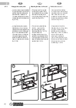
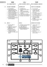
PROGRAMMAZIONE COMANDO A  

PARETE WIRELESS B1012

Queste operazioni consentono 

di modificare alcuni parametri di 

funzionamento impostati da OLIMPIA 

SPLENDID in fase di realizzazione 

del dispositivo. 

Per attivare la modalità di 

programmazione parametri premere 

e mantenere premuto per almeno 3 

secondi il tasto ON/Standby (tasto 

1) e il tasto di attivazione deflettore 

aria (tasto 4).

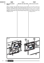
L’attivazione della funzione di 

programmazione è segnalata dal 

lampeggio del simbolo dell’unità di 

misura della temperatura.

A questo punto è possibile 

modificare:

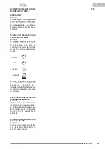
- l’unità di misura °C o °F, con cui  

  viene visualizzata la temperatura  

  desiderata, tramite la pressione  

  del tasto di attivazione ricircolo  

  aria (tasto 3).

- i valori di minimo e massimo  

  della temperatura ambiente,  

  selezionabili premendo  il tasto  

  di attivazione deflettore  

  aria (tasto  4). In particolare,  

  il valore massimo o minimo di  

  temperatura impostabile  

  è indicato rispettivamente  

  dall’accensione di due pallini o 

  di un pallino a lato dei valori  

  impostati e visualizzati.   

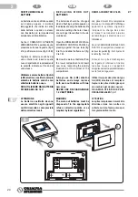
  Questi sono poi modificabili  

  premendo i tasti incremento/ 

  decremento temperatura (tasti  

 5/6).

P e r   u s c i r e   d a l l a   f u n z i o n e 

programmazione e memorizzare i 

dati impostati premere il tasto ON/

standby (tasto 1).  


Le impostazioni effettuate con 

queste operazioni rimangono 

memorizzate per circa 30 secondi, 

anche in assenza di batterie (con 

display spento). E’ possibile quindi 

mantenere le personalizzazioni 

impostate anche in caso di 

sostituzione delle batterie, solo se 

tale operazione viene effettuata entro 

questo tempo limite. In caso contrario 

le personalizzazioni memorizzate 

saranno cancellate e verranno 

automaticamente ripristinate le 

impostazioni di fabbrica (temperatura 

impostabile tra 18°C e 30°C).

4.1

PROGRAMMING THE WIRELESS 

B1012 WALL-MOUNTED CON-

TROL PANEL

This operation allows some of 

the OLIMPIA SPLENDID factory 

settings to be modified. 

To enter the parameters 

programming mode, first press the 

air flow direction activation key (key 

4) followed by the ON/Stand-by key 

(key 1) for at least 3 seconds.

The symbol of the unit air 

temperature starts to blink 

when the programming mode is 

activated. 

When this happens, the following 

can be modified:

-  the unit of measurement °C 

  or °F (identifying the temperature  

  measurement system)  by  

  pressing the air recirculation  

  activation key (key 3).

-  the minimum and maximum room  

  temperatures, which can be  

  chosen by pressing the air flow  

  direction activation key  (key 4).  

  The minimum or maximum  

  temperatures that can be set are  

  indicated by either one or two  

  small dots lighting up beside  

  the displayed set values.

  These can then be changed  

  by pressing the temperature  

  increase/decrease keys (keys  

  5/6).  

To exit the programming mode and 

store the set information, press the 

ON/Stand-by key (key 1).

The settings entered during 

this operation are stored for 

approximately 30 seconds even if 

no batteries are inserted (display 

off). Therefore, if the batteries need 

changing, the personalised settings 

can only be kept if the batteries 

are replaced within this period of 

time. Should this not be possible, 

the personalised settings will be 

deleted and automatically replaced 

by the default settings (temperature 

set between 18°C and 30°C).

PROGRAMMATION COMMANDE 

MURALE SANS FIL B1012

Ces opérations permettent de 

modifier un certain nombre de 

paramètres de fonctionnement 

paramétrés par OLIMPIA SPLENDID 

en phase de réalisation du dispositif.

P o u r   a c t i v e r   l e   m o d e   d e 

programmation des paramètres 

maintenir enfoncé pour au moins 

3 secondes la touche ON/Veille 

(touche 1) et la touche d’activation 

déflecteur air (touche 4).

L’activation de la fonction de 

programmation est signalée par le 

clignotement du symbole de l’unité 

de mesure de la température.

A ce point, il est possible de modifier :

- l’unité de mesure °C ou °F,  

  avec laquelle est affichée la  

  température souhaitée, par  

  pression de la touche d’activation  

  recyclage air (touche 3).  

-  les valeurs minimale et   

  maximale de  


  température ambiante,   

  sélectionnables en  


  appuyant sur la touche   

  d’activation déflecteur air 

  (touche 4).  


  En particulier, la valeur  maximale  

  ou minimale de température  

  paramétrable est indiquée  

  respectivement par l’allumage de  

  deux boules ou d’une boule en  

  regard des valeurs paramétrées  

  et affichées. 

  Celles-ci sont modifiables  

  en appuyant sur les touches  

  augmentation/diminution  

  température (touches 5/6).   


P o u r   q u i t t e r   l a   f o n c t i o n 

programmation et mémoriser les 

données paramétrés, appuyer sur la 

touche ON/veille (touche 1).

Les paramétrages effectués avec ces 

opérations restent mémorisées pendant 

environ 30 secondes, même en l’absence 

de piles (dispositif d’affichage éteint). Il 

est possible par conséquent de maintenir 

les personnalisations paramétrées 

même en cas de remplacement des 

piles, seulement si cette opération est 

effectuée dans ce temps limite. Dans 

le cas contraire, les personnalisations 

mémorisées seront effacées et les 

p a r a m é t r a g e s   d ’ u s i n e   s e r o n t 

automatiquement rétablis (température 

paramétrable entre 18°C et 30°C).

Summary of Contents for B1012

Page 1: ...ISTRUZIONI PER INSTALLAZIONE E MANUTENZIONE INSTALLATION AND MAINTENANCE INSTRUCTION INSTRUCTIONS POUR L INSTALLATION ET LA MAINTENANCE INSTRUCCIONES DE INSTALACI N Y USO I GB F SP...

Page 2: ...alculations tamperingbyunauthorised personnel replacement of worn out batteries THE MANUFACTURER ASSUMES NO LIABILITY FOR DAMAGES TO GOODSORPERSONSRESULTING FROMFAILURETOCOMPLYWITH THE INSTRUCTIONS CO...

Page 3: ...autorizado sustituci n de las bater as agotadas LA EMPRESA CONSTRUCTORA NO ASUME NINGUNA RESPON SABILIDAD POR DA OS A PER SONAS O COSAS QUE DERIVEN DE LA INOBSERVANCIA DE LAS NORMAS CONTENIDAS EN EL P...

Page 4: ...ervice or in the store at which you bought the product This regulation is valid only in EU member states SYMBOLS Thesymbolscontainedinthischapter provide quick and clear information for the correct an...

Page 5: ...ritos en el si guientecap tulopermitenobteneren formar pidayun vocalainformaci n necesariaparalacorrectainstalaci n y uso del aparato en condiciones de seguridad Pictogramas presentes en el texto Serv...

Page 6: ...y designed that is to control temperatures in the rooms where it is installed All other uses are inappro priate and therefore dange rous The manufacturer shall not be held responsible for possible dam...

Page 7: ...e para el uso para el que ha sido expresamente concebido es decir para controlar la temperatura en los ambientes en los que est instalado Cualquier otro uso se debe considerar im propio y por lo tanto...

Page 8: ...ection procedures for individual parts in accordance with local regulations Furthermore ensure that those parts of the device which could constitute a danger especially for children who might regard t...

Page 9: ...a componente seg n las disposiciones legales locales Asimismo se recomienda volver inocuas las partes del aparato que puedan constituir un peligro especialmente para los ni os que podr an utilizar el...

Page 10: ...ansmission encoding selectors WARNINGS Installation must be carried out by qualified personnel All instructions contained in this manual must be adhered to Failure to do so can lead to the malfunction...

Page 11: ...de codificaci n de transmisi n ADVERTENCIAS La instalaci n debe ser realizada por personal cualificado Es indispensable aplicar todas las nociones indicadas en el presente manual Su no aplicaci n pued...

Page 12: ...LR6 type dry alkaline 1 5V Open the WIRELESS B1012 WALL MOUNTED CONTROL PANEL by pressing against the tabs fig 2 ref A and slide the frame out fig 2 ref B Insert the batteries in the lower compartmen...

Page 13: ...LR6 alcalinas secas de 1 5 V Abra el CONTROL DE PARED INAL MBRICO B1012 ejerciendo una presi n sobre las dos leng etas fig 2 ref A y extraiga el marco fig 2 ref B Las bater as se deben introducir en...

Page 14: ...To do this set the same communication encoding on the selectors on both the devices use a pointed tool if necessary It is also possible to associate one or more WIRELESS B1012 WALL MOUNTED CONTROL PA...

Page 15: ...unicaci n en los selectores presentes en ambos dispositivos si es necesario utilice una herramienta puntiaguda De esta forma tambi n es posible combinar uno o m s CONTROLES DE PARED INAL MBRICOS B1012...

Page 16: ...ance of at least 10 15 cm from furniture or walls including ceiling and floor and at least 160 170 cm from the air conditioner is advised WARNING Before proceeding with mounting the device on the wall...

Page 17: ...se recomienda mantener una distancia de al menos 10 15 cm de muebles y de otras paredes y una altura de aproximadamente 160 170 cm del suelo ATENCI N Antes de proceder a la instalaci n del dispositiv...

Page 18: ...A C B 2 2 5 MOUNTING ON THE WALL Unscrew the two screws fig 5 ref A and separate the card support fig 5 ref B from the base fig 5 ref C WARNING Handle the card support with care so as not to damage t...

Page 19: ...NTAJE EN LA PARED Desenrosque los dos tornillos fig 5 ref A y separe el soporte de la tarjeta fig 5 ref B de la base fig 5 ref C ATENCI N Manipule con cuidado el soporte de la tarjeta para no da ar la...

Page 20: ...erting them in the corresponding slots of the electric box fig 6ref A If it is to be mounted directly onto the wall mark the two mounting holes in the desired position fig 7 ref A using the base as a...

Page 21: ...las ranuras correspondientes a los orificios de la caja fig 6 ref A si la instalaci n se debe realizar directamente a la pared trace en la posici n previamente identificada los dos orificios de fijac...

Page 22: ...B 8 A B B 2 2 6 MOUNTING THE CARD SUPPORT Mount the base to the wall then mount the card support fig 8 ref A inserting the lower grips into the lower slots on the base then tighten the two clamping s...

Page 23: ...JETA Una vez terminada la fijaci n de la base a la pared coloque el soporte de la tarjeta fig 8 ref A introduciendo los dientes de enganche inferior en las ranuras de la base a continuaci n enrosque l...

Page 24: ...pressing against the two tabs fig 9 ref A and slide the frame out fig 9 ref B Remove the worn out batteries from the lower compartment and insert new ones respecting the polarity illustrated at the b...

Page 25: ...s leng etas fig 9 ref A y extraiga el marco fig 9 ref B Quite las bater as descargadas del compartimiento inferior e introduzca las nuevas respetando estrictamente la polaridad indicada en el fondo de...

Page 26: ...maximum and automatic 3 Air recirculation Kit optional on off key 4 Air flow direction on off key 5 Increase room temperature key 6 Decrease room temperature DISPLAY 7 Batteries running low indicator...

Page 27: ...opcional 4 Bot n de activaci n desactivaci n movimiento deflector de aire 5 Bot n de aumento temperatura ambiente deseada 6 Bot n de disminuci n temperatura ambiente deseada DISPLAY 7 Indicador de ba...

Page 28: ...e fan speed moves between minimum medium maximum automatic In Automatic mode the air conditio ner ventilation speed depends on the difference between the detected room temperature and the desired and...

Page 29: ...idad de ventilaci n entre los siguientes modos m nima media m xima autom tica En modo autom tico la velocidad de ventilaci n del acondicionador depende de la desviaci n de la temperatura ambiente dete...

Page 30: ...ure limits refer to the factory settings and can be changed as shown in the section related to the device programming REDUCING THE INDOOR TEM PERATURE Key 6 Allows the indoor temperature to be reduced...

Page 31: ...de f bri ca y son modificables en la forma indicada en el p rrafo dedicado a la programaci n del dispositivo DISMINUCI N TEMPERATURA INTERNA Bot n 6 Permite disminuir 1 C o 2 F la temperatura ambient...

Page 32: ...flow direction activation key key 4 The minimum or maximum temperatures that can be set are indicated by either one or two small dots lighting up beside the displayed set values These can then be chan...

Page 33: ...ra ambiente seleccionables pulsando el bot n de activaci n del deflector de aire bot n 4 En particular el valor m ximo o m nimo de temperatura configurable est indicado respectivamente por el encendid...

Page 34: ...reless B 1011 a cui abbinato Accertarsi di non aver installato il comando a parete o l interfaccia seriale in prossimit di oggetti metallici o conduttivi schermi pareti armate ecc o cablaggi elettrici...

Page 35: ...11 serial interface Make sure the wall mounted control panel and or the serial interface have not been installed near metallic or conductive objects monitors reinforced walls etc or electric cables Ma...

Page 36: ...des de la commande murale REMEDES Ins rer les piles V rifier la bonne insertion des piles polarit Remplacer les piles V rifier la correspondance entre param trages codage commande murale et interface...

Page 37: ...ol de pared y de la interfaz serial inal mbrica B 1011 a la que est combina do Verifique que el control de pared o la interfaz serial no hayan sido instalados cerca de objetos met licos o conductores...

Page 38: ...istema in OFF 18 C 30 C con passi di 1 C 62 F 86 F con passi di 2 F 0 C 45 C RH10 90 senza condensa 10 C 60 C RH 10 90 senza condensa IP20 86x122x27 125 grammi Alimentazione Frequenza radio Portata co...

Page 39: ...th increments of 1 C 62 F 86 F with increments of 2 F 0 C 45 C RH10 90 without condensation 10 C 60 C RH 10 90 without condensation IP20 86x122x27 125 g Power supply Radio frequency Communication rang...

Page 40: ...yst me en OFF 18 C 30 C avec pas de 1 C 62 F 86 F avec pas de 2 F 0 C 45 C RH10 90 sans condensation 10 C 60 C RH 10 90 sans condensation IP20 86x122x27 125 grammes Alimentation Fr quence radio Port e...

Page 41: ...en OFF 18 C 30 C con pasos de 1 C 62 F 86 F con pasos de 2 F 0 C 45 C RH 10 90 sin condensaci n 10 C 60 C RH 10 90 sin condensaci n IP20 86x122x27 125 gramos Alimentaci n Frecuencia radio Alcance comu...

Page 42: ......

Page 43: ......

Page 44: ...277288B...

Reviews: