


6
I
GB
F
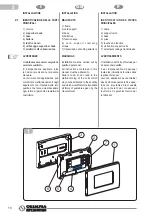
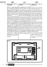
USO PREVISTO
Il COMANDO A PARETE WIRELESS
B1012 consente di controllare il
funzionamento del climatizzatore
al quale è abbinato, a seconda
delle impostazioni selezionate e
visualizzate sul display di cui è
corredato.
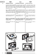
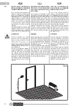
Il COMANDO A PARETE WIRELESS
B1012 deve essere utilizzato
esclusivamente in abbinamento
all’INTERFACCIA SERIALE
WIRELESS B1011 opportunamente
connessa ai climatizzatori OLIMPIA
SPLENDID predisposti.
Tramite questi due componenti
abbinati, il climatizzatore potrà
essere attivato in modo da ottenere
una temperatura ambiente pari a
quella impostata sul comando a
parete.
AVVERTENZE
• Questo apparecchio dovrà
essere destinato solo all’uso
per il quale è stato espressa
mente concepito, e cioè per
gestire la temperatura negli
ambienti dove viene installato.
Ogni altro uso è da considerar
si improprio e quindi pericolo
so.Il costruttore non può esse
re considerato responsabi
le per eventuali danni derivanti
da usi impropri, erronei ed
irragionevoli.
• In caso di guasto e/o di catti
vo funziona mento del siste
ma, spegnerlo e non manomet
terlo. Per l’eventuale ripara
zione rivolgersi esclusivamen
te ai centri di assistenza tec
nica autorizzati dal costruttore
e richiedere l’utilizzo di ricam
bi originali. Il mancato rispetto
di quanto sopra può compro
mettere la sicurezza del siste
ma.
• Non permettete che l’apparec
chio sia usato da bambini o da
incapaci, senza sorveglianza.
• In caso di prolungato periodo
di inattività del COMANDO A
PARETE WIRELESS B1012 si
consiglia di estrarre le batterie
dall’apposito vano.
1.3
1
INTENDED USE
The WIRELESS B1012 WALL-
MOUNTED CONTROL PANEL
controls the air-conditioner to which
it is associated according to the
settings chosen and shown on the
display.
The WIRELESS B1012 WALL-
MOUNTED CONTROL PANEL
should only be used with the
W I R E L E S S B 1 0 11 S E R I A L
INTERFACE duly connected to
OLIMPIA SPLENDID air-conditioners
equipped for the purpose.
By using these two paired units,
the air-conditioner can be used in
such a way that it reaches the room
temperature set on the wall-mounted
control panel.
WARNINGS
• This device should only
be used for the purposes for
which it has been expressly
designed, that is to control
temperatures in the rooms
where it is installed.
All other uses are inappro
priate and therefore dange
rous. The manufacturer shall
not be held responsible for
possible damages deriving
from improper, incorrect or
unreasonable use.
• In the event the system breaks
down and/or malfunctions,
turn it off and do not tamper
with it. If repairs are needed,
refer to authorised technical
service centres only and ask
that only original spare parts
be used. Failure to comply
with the above can
compromise the safety of the
system.
• Do not allow the device to be
used by children or persons
unable to do so without proper
supervision.
• In the event the WIRELESS
B1012 WALL-MOUNTED CON
TROL PANEL is not to
be used for any length of time,
remove the batteries from their
compartment.
UTILISATION PREVUE
La COMMANDE MURALE SANS
FIL B1012 permet de contrôler
le fonctionnement du climatiseur
auquel est associé, selon les
paramétrages sélectionnées et
affichées sur le dispositif d’affichage
dont il est doté.
La COMMANDE MURALE SANS
FIL B1012 doit être utilisée
exclusivement en association avec
l’INTERFACE SÉRIE SANS FIL
B1011 opportunément connectée
a u x c l i m a t i s e u r s O L I M P I A
SPLENDID pré-équipés.
Au moyen de ces deux composants
associés, le climatiseur pourra
être activé de façon à obtenir une
température ambiante égale à
celle paramétrée sur la commande
murale.
AVERTISSEMENTS
• Cet appareil devra être destiné
seulement à l’emploi pour
lequel il a été expressément
conçu, à savoir pour gérer la
température dans les pièces
où est installé. Tout autre em
ploi doit être considéré comme
inapproprié et par conséquent
dangereux. Le fabricant
ne peut pas être tenu pour
responsable des
dommages éventuels dus
à des emplois inappropriés,
erronés et déraisonnables.
• En cas de défaut et/ou de
mauvais fonctionnement
du système, l’éteindre et ne
pas le manipuler. Pour l’éven
tuelle réparation, s’adresser
exclusivement aux centres
d’assistance technique agréés
par le fabricant et demander
l’usage de pièces de rechange
originales. Le non respect des
instructions énoncées ci-
dessus peut compromettre la
sécurité du système.
• Ne pas permettre que l’appareil
soit utilisé par des enfants ou
des incapables, sans
surveillance.
• En cas de période prolongée
d’inactivité de la COMMANDE
MURALE SANS FIL B1012, il
est conseillé de sortir les piles
de leur logement.


