APPLIED OPERATIONS
/Image Acquisition
2-56
Page
1 Setting the Z-direction scanning range
While acquiring image, move the Z stage according to the range of the multiple sections
to be observed (Z-direction scanning range).
From the panel page tabs shown on the bottom right of the [Acquire] panel, select the [Z
Stage] sub-panel.
The moving amount assigned to the <Z stage fine adjustment> and <Z
stage coarse adjustment> buttons can be changed.
See section 1-3 in MAINTENANCE, “Setting the System Configuration” for
detailed operations.
1.
Check the [Locked] check box in the [Z Stage] sub-panel.
Do not turn the fine focus adjustment knob while the [Locked] check
box is checked, for this may damage the Z motor.
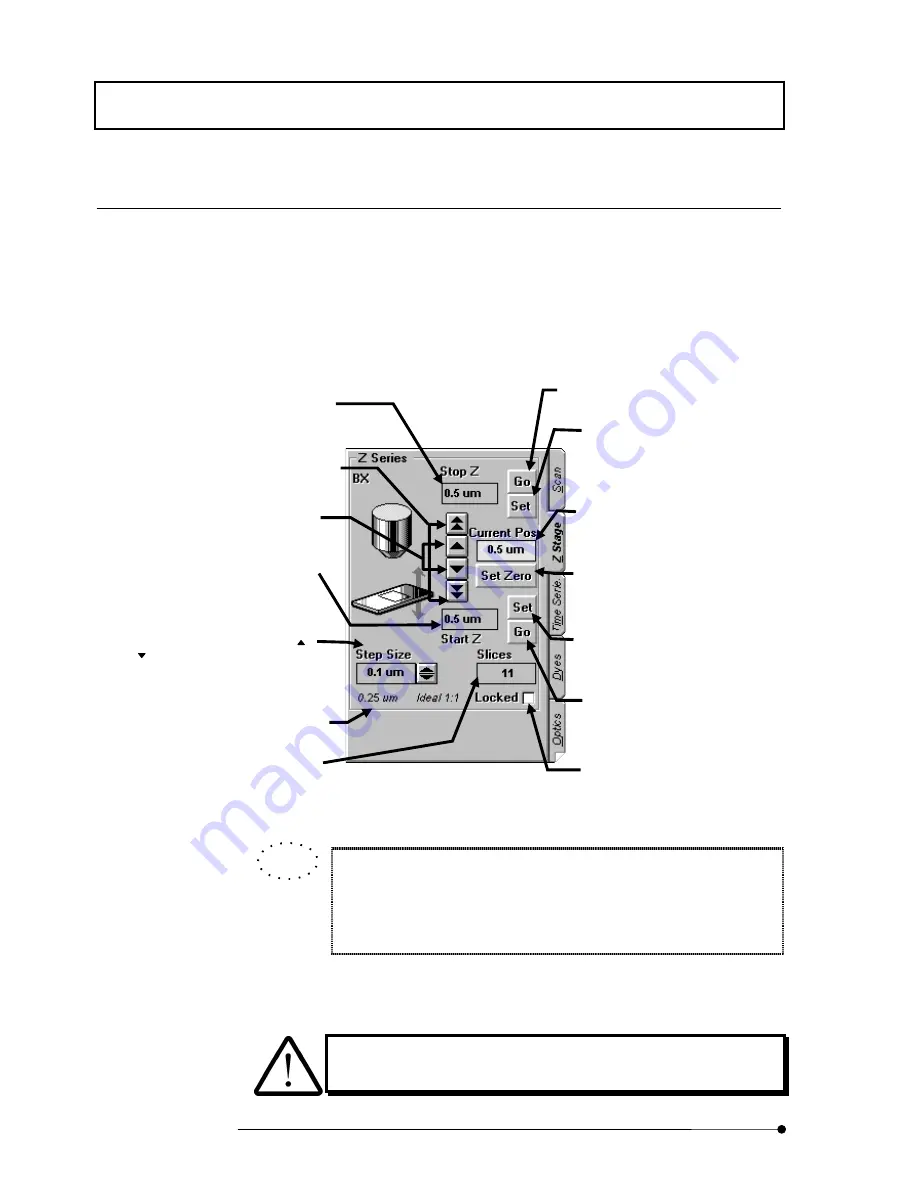
Fig. 2-18 [Z Stage] Sub-panel
<Z stage fine adjustment> buttons
Displaces the Z stage on a fine
scale.
<Z stage coarse adjustment> buttons
Displaces the Z stage on a large scale.
[Current Pos] text box
Shows the current position of the stage.
<Set Zero> button
Sets the current stage position as the
home position. Pressing this button also
clears the [Stop Z] and [Start Z] values.
[Stop Z] text box
Shows the scan stop position in the
range of the observed cross-section (Z-
direction scanning range).
[Start Z] text box
Shows the scan start position in the
range of the observed cross-section (Z-
direction scanning range).
<Set> button
Sets the current stage position as the
scanning start position of the range of
the observed cross-section (Z-direction
scanning range).
<Set> button
Sets the current stage position as the
scanning stop position of the range of
the observed cross-section (Z-direction
scanning range).
[Slices] text box
Shows the number of images acquired.
This number can also be input directly
from the keyboard.
[Step Size] text box
Set the number of steps using the <
>
or <
> button. This number can also
be input directly from the keyboard.
<Go> button
Moves to the set scanning stop position.
Use this button to check the scanning
stop position.
<Go> button
Moves to the set scan start position.
Use this button to check the scan start
position.
[Locked] check box
Enables the Z-Motor operation.
Recommended step size
Shows the number of steps calculated
by the system so that the scale of depth
in the Z-direction of the acquired image
is identical to the scale of the plane in
the X- and Y-directions.
TIP
Summary of Contents for FLUOVIEW FV500
Page 2: ......
Page 8: ......
Page 10: ......
Page 24: ......
Page 110: ......
Page 327: ...APPLIED OPERATIONS Viewing 3D Image 2 217 Page Fig 2 106 Panel Showing Stereo 3D Images ...
Page 396: ......
Page 402: ......
Page 414: ......
Page 420: ......
Page 426: ......
Page 428: ......
Page 430: ......
Page 458: ......
Page 460: ......
Page 462: ......
Page 468: ......
Page 469: ......


