APPLIED OPERATIONS/
Image Analysis
2-188
Page
6.
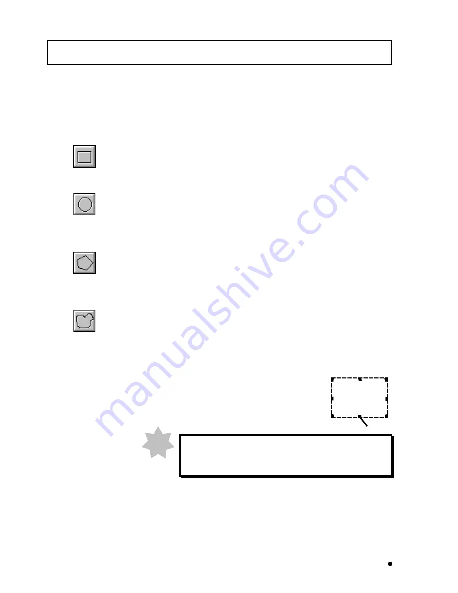
Specify the region to be checked in the image in the [Display] panel.
They can be specified as described below.
z
To specify a rectangle:
On the image, drag the mouse pointer along the diagonal line of the desired
rectangle, from the top left corner to the bottom right corner.
z
To specify a circle or ellipse:
On the image, assume a rectangle circumscribing the circle to be checked
and drag the mouse pointer along the diagonal line between opposite corners
of the rectangle.
z
To specify a polygonal region:
On the image, click the points corresponding to the corners of the polygon to
be checked. After clicking the last corner point, click the right button of the
mouse to connect the last clicked point to the first clicked point.
z
To specify a free region:
On the image, specify a region by dragging. Then release the mouse button
to complete dragging. The point where the dragging was ended will be
connected to the point where it was started.
A region is displayed on the image together with handles on
the perimeter. The region is selected as the target of the
bird’s eye view while the handles are displayed.
If the mouse is clicked in other place than inside the region
specified on the image, the handles will disappear. The bird’s eye
view cannot be displayed while the handles are not displayed.
<Rectangular> button
<Circle> button
<Polyregion> button
<Free Region> button
Handle
NOTE
Summary of Contents for FLUOVIEW FV500
Page 2: ......
Page 8: ......
Page 10: ......
Page 24: ......
Page 110: ......
Page 327: ...APPLIED OPERATIONS Viewing 3D Image 2 217 Page Fig 2 106 Panel Showing Stereo 3D Images ...
Page 396: ......
Page 402: ......
Page 414: ......
Page 420: ......
Page 426: ......
Page 428: ......
Page 430: ......
Page 458: ......
Page 460: ......
Page 462: ......
Page 468: ......
Page 469: ......


