APPLIED OPERATIONS
/Merger/Extraction of Image Channels
2-251
Page
4.
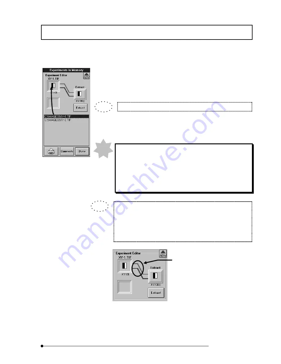
From the file list in the [Experiments in Memory] dialog box, select the file name of
the image from which to extract channels and drag it into the frame at the top left
of the [Experiment Editor] group box. The icon of the image is displayed in the
frame at the top left of the [Experiment Editor] group box.
The mouse pointer turns into the image icon during dragging.
5.
The channels of the image set in the [Experiment Editor] group box are connected
to [Extract] by lines.
The lines of channels are colored as shown below.
Ch1: Navy blue
Ch2: Light blueCh3: Green
Ch4: Yellow green
Ch5: Orange
Ch6: Red
When the mouse pointer is approached to the icon-side end of a line
connected to [Extract], the color of the line end turns into yellow. Clicking
the line in this condition switches the channel between the selected and
deselected status alternately. The lines connected to [Extract] indicate the
selected channels.
Clicking a channel line in this area switches the
channel between the selected and deselected
status.
NOTE
TIP
TIP
Summary of Contents for FLUOVIEW FV500
Page 2: ......
Page 8: ......
Page 10: ......
Page 24: ......
Page 110: ......
Page 327: ...APPLIED OPERATIONS Viewing 3D Image 2 217 Page Fig 2 106 Panel Showing Stereo 3D Images ...
Page 396: ......
Page 402: ......
Page 414: ......
Page 420: ......
Page 426: ......
Page 428: ......
Page 430: ......
Page 458: ......
Page 460: ......
Page 462: ......
Page 468: ......
Page 469: ......


