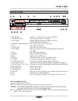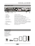
RF IN
RF OUT
LEFT
RIGHT
VIDEO
Y
CB / PB
CR / PR
OPTICAL
COAXIAL
5.1 CH AUDIO OUT
FL
FR
SL
SR
CENTER
SUB-WOOFER
S-VIDEO
2 CH AUDIO IN
YUV/P-SCAN/
DIGITAL AUDIO OUT
VIDEO
S-VIDEO
VIDEO OUT
VIDEO IN
USB
RF IN
RF OUT
LEFT
RIGHT
VIDEO
Y
CB / PB
CR / PR
OPTICAL
COAXIAL
5.1 CH AUDIO OUT
FL
FR
SL
SR
CENTER
SUB-WOOFER
S-VIDEO
2 CH AUDIO IN
YUV/P-SCAN/
DIGITAL AUDIO OUT
VIDEO
S-VIDEO
VIDEO OUT
VIDEO IN
USB
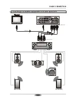
BASIC CONNECTION
07
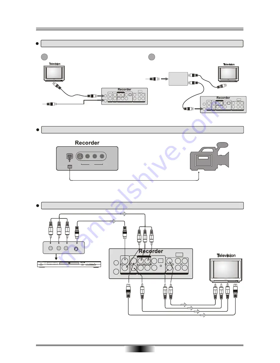
To record from an analog cable TV signal, connect the cable to the RF In jack.
Note: By this connection, you must set the unit standby when watching TV only(B mode).
ANTENNA or
TV signal cable
A
B
SPLITTER
Traditional RF Connection
RF Connection When Using A Splitter Box
To connect devices that you will be recording from DV
DV
S-VIDEO
VIDEO
AV2 IN
L
R
DV IN
RF IN
RF OUT
LEFT
RIGHT
VIDEO
Y
CB / PB
CR / PR
OPTICAL
COAXIAL
5.1 CH AUDIO OUT
FL
FR
SL
SR
CENTER
SUB-WOOFER
S-VIDEO
2 CH AUDIO IN
YUV/P-SCAN/
DIGITAL AUDIO OUT
VIDEO
S-VIDEO
VIDEO OUT
VIDEO IN
USB
If the TV has an S-video input,
When using an S-video cable, do not connect the yellow video cable.
connect the DVD player to the TV with an S-video cable
To record from devices such as DVD Players using the rear connections
Red
White
Yellow
Red White
DVD PLAYER
DS-N809
DVD Video/DVD Audio/VCD/HDCD/JPEG/MP3 PLAYER
To audio input(red,white)
To video input(yellow)
L
R
VIDEO
S-VIDEO
Yellow
To audio input(red,white)
To video input(yellow)
To S-video input
To S-video input
Note: In the DV state, when opening the DV camera, you need wait for 15 seconds. The image will appear
on the screen.
Summary of Contents for DVR-250
Page 1: ......
Page 5: ...03...
Page 6: ...04 The pickup may be condensed with water under the following situation...


