Inputs and VCAs
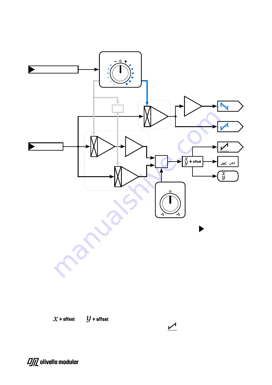
Block diagram (one channel)
SIGNOS has
four inputs
(two per channel) marked with black triangles pointing at their
respective jacks. All of them are DC-coupled, meaning that they accept both audio and CV
signals.
There are two types of inputs:
main inputs
and
modulation inputs
.
Main inputs
These
receive the signals that will actually get proccesed
by SIGNOS.
When unpatched, they’re normalled (internally connected) to 0V. The main inputs are
unattenuated and go straight to their respective channel’s unipolar and bipolar VCAs
(which are controlled by the modulation knobs and modulation inputs, more on that later).
After this step, they get summed with their respective channel’s voltage offset resulting in
the signals and , which are then visually represented by their channel’s
LEDs, sent to the logic and waveshaper circuits and to the
outputs.
SIGNOS
- User Manual | Page 5
INV
MAIN INPUT
MODULATION INPUT
INV
VCA
VCA
MODULATION KNOB
OFFSET KNOB
VCA
+
INV
BIPOLAR VCA
(normalled to -/+5V)
(normalled to 0V)
OUT
OUT
OUT
LED
AND OR
UNIPOLAR
MODULATION
VCA
UNIPOLAR
MODULATION
BIPOLAR
(-5V to +5V)


