26 |
Page
Oliver Machinery
10014 Planer
Dust Collection
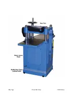
Wood planer can generate a lot of wood shavings and dusts. Connect the dust collection system to this
machine. Minimum CFM requirement for this planer is 600 CFM at the dust port, which means your
dust collection system should have a rating greater than 600 CFM, as air friction from the ducts reduces
the effective CFM at the dust ports.
Wiring and Grounding
DANGER
Deenergize the electrical circuit before touching any enclosed, electrified parts.
Touching electrified part WILL result in serious personal injury or death.
WARNING
All electrical work must be done by a qualified electrician, and must meet the
electrical code in your area.
Make sure the voltage of your power circuit matches the specifications on the
nameplate of the machine, and the circuit is sized to supply power to the planer.
Wiring Instructions
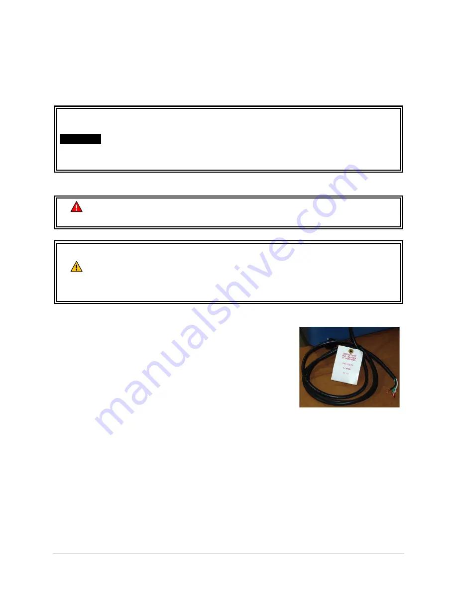
This machine is not pre-wired with a plug. A 7-feet long 14 AWG cord is
provided for connecting this machine to a power source. If you plan to
connect the machine directly to the electrical panel (“Hardwiring”).
Please ensure there is a readily accessible electrical disconnect near
the machine. Refer to section “Wiring Diagram” for wiring your
machine to a power source.
If you choose to connect this machine with a plug and a cord, please
use a UL/CSA listed plug that is sized to meet the amperage
requirement of your machine.
Break-in Period
Congratulations for getting this machine assembled and ready for a test run! Please set a reminder to
service this machine as it goes through the break-in period. Completing these services will maximize the
performance and longevity of your machine.
After 16 hours of operation:
Adjust V-belt tension.
After 50 hours of operation:
Replace gearbox oil.
IMPORTANT
Running this planer without dust collection system, or using a dust collection
system with inadequate suction, will cause dust and shavings to accumulate
inside the planer. This can damage the machine and cause other hazardous
situations. Check your dust collection system regularly to make sure it is not
jammed or filled up.
Summary of Contents for 10014
Page 2: ......
Page 10: ...10 Page Oliver Machinery 10014 Planer Identification...
Page 11: ...10014 Planer OLIVERMACHINERY NET 11 Page...
Page 12: ...12 Page Oliver Machinery 10014 Planer...
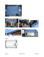
Page 38: ...38 Page Oliver Machinery 10014 Planer Figure 1 Figure 2 Figure 3 Figure 4 Figure 5 Figure 6...
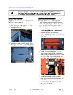
Page 44: ...44 Page Oliver Machinery 10014 Planer between the cutterhead and the feed rollers...
Page 51: ...10014 Planer OLIVERMACHINERY NET 51 Page WiringDiagram...
Page 52: ...52 Page Oliver Machinery 10014 Planer PartsList Table Assembly...
Page 53: ...10014 Planer OLIVERMACHINERY NET 53 Page Cabinet Assembly...
Page 54: ...54 Page Oliver Machinery 10014 Planer Motor Mount Assembly...
Page 55: ...10014 Planer OLIVERMACHINERY NET 55 Page Headstock Assembly...
Page 56: ...56 Page Oliver Machinery 10014 Planer Gearbox Assembly and Dust Port Assembly...
Page 62: ...62 Page Oliver Machinery 10014 Planer MaintenanceRecord Date Task Operator...
Page 63: ...10014 Planer OLIVERMACHINERY NET 63 Page Notes...

