10014 Planer
OLIVERMACHINERY.NET
25
|
Page
4.
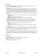
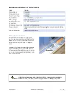
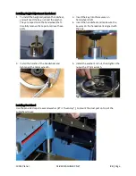
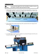
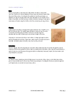
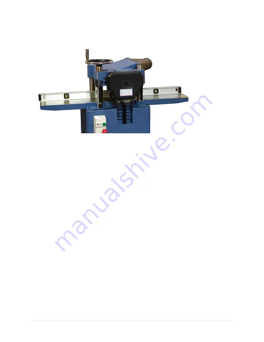
Rotate the set screws with a hex wrench to raise the extension tables. For each set screw, make
small, incremental adjustments, and then move on to the next set screw. Repeat until both
extension tables are in parallel with the planer bed. If a set screws become too difficult to turn, you
may need to slightly loosen the mounting bolts before continue to raise the extension table.
5.
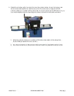
When the extension tables are in parallel with the planer bed, tighten all mounting bolts.
Recheck table parallelism for one more time.
6.
Save these instructions as the extension tables will need to be adjusted from time to time.
Summary of Contents for 10014
Page 2: ......
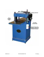
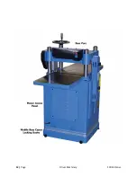
Page 10: ...10 Page Oliver Machinery 10014 Planer Identification...
Page 11: ...10014 Planer OLIVERMACHINERY NET 11 Page...
Page 12: ...12 Page Oliver Machinery 10014 Planer...
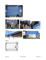
Page 38: ...38 Page Oliver Machinery 10014 Planer Figure 1 Figure 2 Figure 3 Figure 4 Figure 5 Figure 6...
Page 44: ...44 Page Oliver Machinery 10014 Planer between the cutterhead and the feed rollers...
Page 51: ...10014 Planer OLIVERMACHINERY NET 51 Page WiringDiagram...
Page 52: ...52 Page Oliver Machinery 10014 Planer PartsList Table Assembly...
Page 53: ...10014 Planer OLIVERMACHINERY NET 53 Page Cabinet Assembly...
Page 54: ...54 Page Oliver Machinery 10014 Planer Motor Mount Assembly...
Page 55: ...10014 Planer OLIVERMACHINERY NET 55 Page Headstock Assembly...
Page 56: ...56 Page Oliver Machinery 10014 Planer Gearbox Assembly and Dust Port Assembly...
Page 62: ...62 Page Oliver Machinery 10014 Planer MaintenanceRecord Date Task Operator...
Page 63: ...10014 Planer OLIVERMACHINERY NET 63 Page Notes...

