46 |
Page
Oliver Machinery
10014 Planer
6.
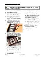
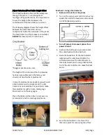
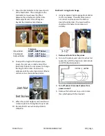
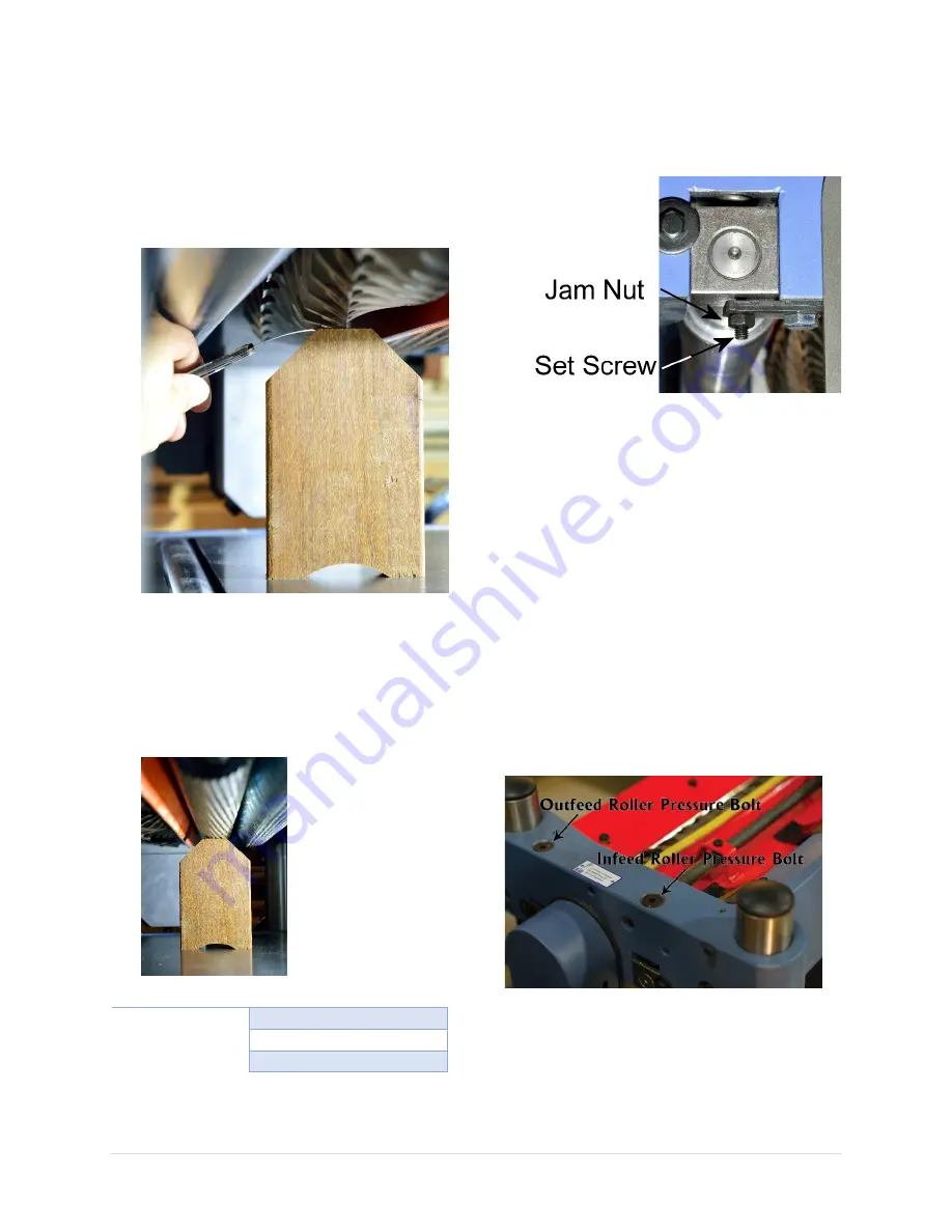
Raise the headstock, place the gauge block
below the cutterhead. For checking the
infeed roller’s offset, put the
0.020”
feeler
gauge on top of the gauge block.
7.
Lower the cutterhead until the lowest point
of the cutterhead barely touches the feeler
gauge.
8.
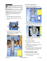
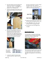
Remove the feeler gauge and move the
gauge block under the infeed roller. The
gauge block should fit right under the
infeed roller if the height setting is perfect.
You may need to rotate the infeed roller to
find the lowest spot. Made adjustments
according to specifications as needed:
Tolerance
Infeed Roller
0.020” - 0.027”
below
Chip breaker
0.000” - 0.020” below
Outfeed Roller
0.024” - 0.031” below
9.
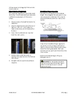
To adjust the height of the feed rollers,
loosen the jam nuts on both ends of the
feed roller. Rotate the set screws to change
the height of the roller. Continue to
calibrate until the cutterhead-roller offset is
uniform across the entire feed roller.
10.
When the correct height is set, hold the set
screws in place and re-tighten the jam nuts.
11.
Repeat
STEP 7-13
for the outfeed roller,
and use a 0.030” feeler gauge instead.
12.
Re-install belt cover when adjustments
complete.
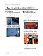
Adjust Feed Roller Tension
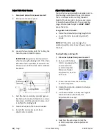
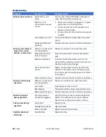
If your workpiece is slipping and not feeding
through the machine, increase the feed roller
pressure by turning the pressure bolts
clockwise with a hex wrench.
There is a pressure adjustment bolt on each end
of the feed rollers. Make sure the adjustments
are made on BOTH ends of the feed roller, so
even pressure is applied across the entire feed
roller.
Summary of Contents for 10014
Page 2: ......
Page 10: ...10 Page Oliver Machinery 10014 Planer Identification...
Page 11: ...10014 Planer OLIVERMACHINERY NET 11 Page...
Page 12: ...12 Page Oliver Machinery 10014 Planer...
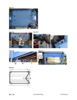
Page 38: ...38 Page Oliver Machinery 10014 Planer Figure 1 Figure 2 Figure 3 Figure 4 Figure 5 Figure 6...
Page 44: ...44 Page Oliver Machinery 10014 Planer between the cutterhead and the feed rollers...
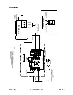
Page 51: ...10014 Planer OLIVERMACHINERY NET 51 Page WiringDiagram...
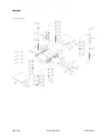
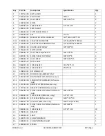
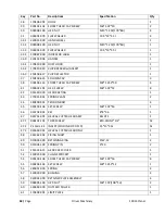
Page 52: ...52 Page Oliver Machinery 10014 Planer PartsList Table Assembly...
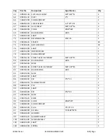
Page 53: ...10014 Planer OLIVERMACHINERY NET 53 Page Cabinet Assembly...
Page 54: ...54 Page Oliver Machinery 10014 Planer Motor Mount Assembly...
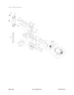
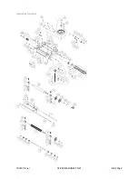
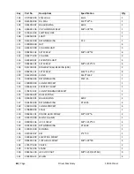
Page 55: ...10014 Planer OLIVERMACHINERY NET 55 Page Headstock Assembly...
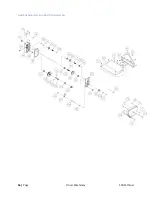
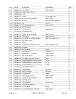
Page 56: ...56 Page Oliver Machinery 10014 Planer Gearbox Assembly and Dust Port Assembly...
Page 62: ...62 Page Oliver Machinery 10014 Planer MaintenanceRecord Date Task Operator...
Page 63: ...10014 Planer OLIVERMACHINERY NET 63 Page Notes...

