background image

10014 Planer 

OLIVERMACHINERY.NET 

49


|

 Page 

Problem 

Possible Cause 

Possible Solution 

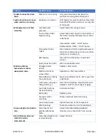
Unable to move feed rate 

knob. 

Machine is not running.  Only move feed rate knob while the 

machine is running idle at full speed. 

Feed rollers does not move 

when machine is running. 

Gear box is in neutral. 

Shift feed rate control knob to set feed rate 
to 16/20 FPM while machine is running idle 
at full speed. 

Workpiece does not feed 

smoothly. 

Low feed roller 

pressure. 

Adjust feed roller spring tension.  

Incorrect feed roller 

height setting. 

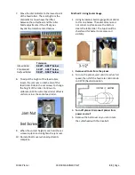
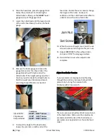
Adjust feed rollers height so the bottom of 
the rollers is below the lowest point of the 
cutterhead. 
 
Infeed Roller: 0.020” - 0.027” below. 
Outfeed Roller: 0.024” - 0.031” below. 

Dirty planer table / 

rollers. 

Clean table and rollers. Apply paste wax on 
the table to reduce drag. Do not use silicon 
lubrications on table top. 

Belt slipping 

Clean belt and the pulleys. Adjust belt 
tension. 

Stuck planer bed roller.  Clean and lubricate roller.  

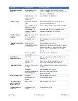
Machine vibrates 

excessively or makes 

unexpected noise. 

Damaged cutter 

inserts. 

Replace cutter inserts. 

Machine stands on 

uneven floor. 

Reposition on flat, level surface. 

Chip deflector is hitting 

the cutterhead. 

Move chip deflector 1/16”- 1/8” away from 
cutterhead.  

V-belt worn, slipping or 

hitting belt cover. 

Clean belt and pulleys. Adjust belt tension. 
Replace V-belt if it shows signs of aging. 

Feed roller bushing 

needs lubrication. 

Lubricate bushings. 

Bent pulley 

Replace pulley. 

Improper motor 
mounting. 

Check and adjust motor mounting. 

Loose components. 

Tighten fasteners of the component.  

Worn bearings 

Contact customer service for assistance. 

Uneven depth of cut side to 

side. 

Cutterhead is not 

parallel with planer 

table. 

Adjust cutterhead-table parallelism. 
Tolerance: Less than 0.005” side-to-side. 

Board thickness does not 

match the scale’s 

measurement.  

Cutterhead height scale 

is mispositioned. 

Adjust the scale. 


Summary of Contents for 10014

Page 1: ...4 Owner s Manual For Models Manufactured Since 02 2020 175370 Oliver Machinery 1 800 559 5065 6902 S 194th St Kent WA 98032 info olivermachinery net WWW OLIVERMACHINERY NET Stock Number 10014 201 Manu...

Page 2: ......

Page 3: ...ACHINERY RESERVES THE RIGHT TO EFFECT AT ANY TIME WITHOUT PRIOR NOTICE THOSE ALTERATIONS TO PARTS FITTINGS AND ACCESSORY EQUIPMENT WHICH THEY MAY DEEM NECESSARY FOR ANY REASON WHATSOEVER SAVE THIS MAN...

Page 4: ...mbly 22 Installing Height Adjustment Handwheel 23 Installing Dust Hood 23 Installing Extension Tables 24 Dust Collection 26 Wiring and Grounding 26 Wiring Instructions 26 Break in Period 26 Controls a...

Page 5: ...et 43 Adjust Feed Roller Tension 46 Adjust Cutterhead Height Scale 47 Anti Kickback Fingers Inspection 47 Troubleshooting 48 Wiring Diagram 51 Parts List 52 Table Assembly 52 Cabinet Assembly 53 Motor...

Page 6: ...and photographs in this manual should match the machine delivered If you find any differences or anything that seems confusing in this manual or some instructions are not available please check our w...

Page 7: ...mensions Width x Depth x Height Fully Assembled 47 1 2 L x 29 W x 47 H Footprint 21 L x 22 W Fully Assembled Weight 401 lbs Shipment Info Type Wood Crate with Pallet Base Content Planer with Included...

Page 8: ...ck Cutterhead Type Helical Cutterhead Diameter 2 5 8 Cutterhead Speed 5000 RPM Number of Cutter Inserts 52 Number of Rows of Cutter Inserts 4 Cutter Insert Type Four sided indexable German made carbid...

Page 9: ...Material Precision ground cast iron Bed Roller Two Extension Table Weight 21 lbs Safety Number of Dust Ports 1 Dust Port Size 4 Minimum CFM Required 600 CFM Sound Rating 2 distance 85 dB Others Serial...

Page 10: ...10 Page Oliver Machinery 10014 Planer Identification...

Page 11: ...10014 Planer OLIVERMACHINERY NET 11 Page...

Page 12: ...12 Page Oliver Machinery 10014 Planer...

Page 13: ...dure indicated in the electrical code of your area 3 DISCONNECT the machine from power before performing any service maintenance or adjustments A machine under repair should be RED TAGGED to show it s...

Page 14: ...delines Specific to Planer Before Work Begin 1 USE ONLY NATURAL SOLID WOOD Do not plane any material such as plywood MDF OSB laminate or anything that can disintegrate during operation Do not plane tr...

Page 15: ...back Never start the machine with the workpiece engaging the cutterhead Never start feeding until the planer has reached its full speed Ensure there is proper gripping force from the feeding rollers w...

Page 16: ...function or breakdown This machine must be connected to the grounding conductor when available and all grounding connections must meet or exceed the electrical code requirements in your area Furthermo...

Page 17: ...14 12 10 12 to 15 12 12 10 10 15 to 20 10 10 10 NR 21 to 30 10 NR NR NR NR Not Recommended WARNING Use properly sized wires that meet or exceed the power requirement of your machine Using undersized...

Page 18: ...utlet is installed nearby the machine Please refer to the Electricals section in this manual for details regarding electrical requirements and safety instructions Lighting Adequate lighting is needed...

Page 19: ...delivery please be sure help is available to move the machine to its final location WARNING 10014 Planer has a gross weight of 470 lbs and a net weight of 401 lbs Safe moving techniques and proper li...

Page 20: ...Cap Screw M6 1 0P 12 Washer 6 each 8 4mm Hex Wrench 1 9 10 13mm Wrench 1 10 Cast Iron Extension Tables 2 11 4 Dust Hood Not shown in the picture 1 NOTICE If you cannot find the item in the list above...

Page 21: ...50 55 lbs inch T25 Star Bit Socket Cutter inserts installation Removing Machine from Crate When all items are ready for setting up the machine gently remove the machine from the pallet The planer is...

Page 22: ...rust preventive such as Boeshield T 9 or paste wax Do not use rust preventives that contains silicon which is known to interfere with certain finishes and glues Assembly This planer is mostly assembl...

Page 23: ...to retrieve these parts 2 Install the handle of the handwheel and tighten with a 14mm wrench 3 Insert the key into the keyway on handwheel shaft 4 Insert the handwheel and make sure the keyway on the...

Page 24: ...hand thread the set screws into the extension table 2 Align the edge of extension tables with the edge of the planer bed Make sure the edges are flush with each other 3 Use a straight edge to check if...

Page 25: ...extension tables are in parallel with the planer bed If a set screws become too difficult to turn you may need to slightly loosen the mounting bolts before continue to raise the extension table 5 Whe...

Page 26: ...ovided for connecting this machine to a power source If you plan to connect the machine directly to the electrical panel Hardwiring Please ensure there is a readily accessible electrical disconnect ne...

Page 27: ...ion To Turn On Machine Press the green START button NOTICE The machine will only start when the STOP button is reset Cutterhead Height Adjustment The cutterhead height adjustment handwheel is located...

Page 28: ...toggle between absolute measuring mode and incremental mode Value in INC mode will be reset when switching to ABS mode To reset the reading to zero in ABS mode hold the ON OFF button Feed Rate Control...

Page 29: ...er it will engage the infeed roller C The infeed roller will bring the workpiece towards the chip breaker D and the cutterhead E 4 As the cutterhead cuts on the workpiece the woodchips will be broken...

Page 30: ...headstock all the way up Ensure all the anti kickback fingers can move freely 4 Turn on the DRO to check the readings of digital readout The readings should reflect the movement of the headstock 5 Pr...

Page 31: ...ber Use metal detector to scan for metal as needed Check Moisture Content Check moisture content of the workpiece before operation Green wood with moisture content over 20 will not cut properly and ma...

Page 32: ...kpiece that is hard brittle reduce the depth of cut and feed rate For your reference this Janka scale shows the hardness of wood types that are commonly used It ranks the hardness of various wood type...

Page 33: ...dusk mask to avoid inhaling harmful airborne particles With the above preparation steps completed the workpiece is ready for planing 1 Please put on all protection devices before proceed If you have...

Page 34: ...n a few passes with deeper cuts then finish with a light pass with shallow cuts and slow feed rate 8 Turn on the digital readout DRO and use the INC mode to measure the depth of cut for each pass If y...

Page 35: ...his case moistening the problematic area before planing can sometimes mitigate the issue Chipping can also cause by dirty or dull cutters If chipping happens while planing straight grain stocks Inspec...

Page 36: ...WARNING Using unapproved accessories may cause machine to malfunction resulting in serious injury and or machine damage Only use accessories recommended for this machine Cutter Inserts Genuine four si...

Page 37: ...er bed Adjust as needed Every month Check V belt tension and replace if belt shows signs of cracking or glazing Every 4 6 months Remove dust buildups from motor and the cabinet Inspect table chain for...

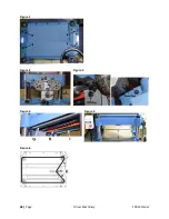
Page 38: ...38 Page Oliver Machinery 10014 Planer Figure 1 Figure 2 Figure 3 Figure 4 Figure 5 Figure 6...

Page 39: ...f the planer Adjust Chip Deflector Clearance The chip deflector was pre installed in the factory and should not require adjustments initially If the gap between chip deflector and cutterhead goes beyo...

Page 40: ...insert platform with a vacuum or compressed air IMPORTANT Obstacles between the insert and cutterhead platform will create uneven pressure against the insert This will lower cut quality and may cause...

Page 41: ...s adjustment 4 Remove the side panels to gain access to the motor mount cap screws 5 Loosen the cap screws and lower the motor to tighten the belt If the belt becomes too tight raise the motor 6 Re ti...

Page 42: ...ng a workpiece through the planer There is no fixed rule for setting the exact height of the table rollers because each piece of wood behaves differently The acceptable range of table roller height is...

Page 43: ...ded you will need a dial indicator with a sturdy stand If a dial indicator is not available it is possible to make the adjustments with a home made gauge block and a set of feeler gauges Clean the tab...

Page 44: ...44 Page Oliver Machinery 10014 Planer between the cutterhead and the feed rollers...

Page 45: ...rate until the cutterhead roller offset is uniform across the entire feed roller 9 When the correct height is set hold the set screws in place and re tighten the jam nuts 10 Re install belt cover when...

Page 46: ...024 0 031 below 9 To adjust the height of the feed rollers loosen the jam nuts on both ends of the feed roller Rotate the set screws to change the height of the roller Continue to calibrate until the...

Page 47: ...pointer is pointing at the exact value as the thickness of the board 5 Re tighten the screws when adjustments complete Anti Kickback Fingers Inspection This planner is equipped with anti kickback fing...

Page 48: ...ed Inspect cutterhead and make sure it is not obstructed by woodchips Check dust port and headstock and clear blockages Too much load on a circuit Make sure the power circuit is sized for this machine...

Page 49: ...e top Belt slipping Clean belt and the pulleys Adjust belt tension Stuck planer bed roller Clean and lubricate roller Machine vibrates excessively or makes unexpected noise Damaged cutter inserts Repl...

Page 50: ...workpiece surface Damaged cutter Rotate replace cutter insert Planing against across grain or knots Avoid planing workpiece with knots Plane along the grain and perform downhill cut whenever possible...

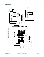
Page 51: ...10014 Planer OLIVERMACHINERY NET 51 Page WiringDiagram...

Page 52: ...52 Page Oliver Machinery 10014 Planer PartsList Table Assembly...

Page 53: ...10014 Planer OLIVERMACHINERY NET 53 Page Cabinet Assembly...

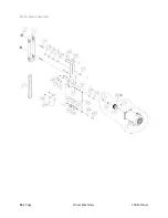
Page 54: ...54 Page Oliver Machinery 10014 Planer Motor Mount Assembly...

Page 55: ...10014 Planer OLIVERMACHINERY NET 55 Page Headstock Assembly...

Page 56: ...56 Page Oliver Machinery 10014 Planer Gearbox Assembly and Dust Port Assembly...

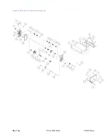
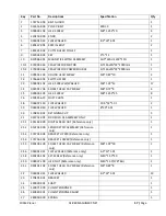
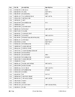
Page 57: ...105 HEX SCREW M8 1 25P 25 8 16 250345 615 DUST CHUTE 1 18 006007 140 FLAT WASHER 10 5 32 1 0t 2 19 006001 040 FLAT WASHER 8 30 3 0t 1 20 170813 901 RETAINING CLIP 3 21 924752 001 DRO SOLD AS ASSEMBLY...

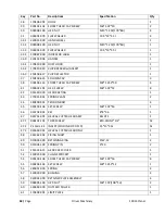
Page 58: ...1 HEX SCREW M6 1 0P 12 8 42 051440 000 HEAD CASTING 1 43 270015 901 SPRING PLATE 2 44 380200 901 TENSION BOLT 4 45 000203 106 SET SCREW M6 1 0P 16 1 46 012204 001 KEY 8 8 36 1 47 924751 001 HELICAL CU...

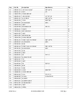
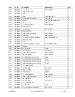
Page 59: ...1 78 150028 000 CHAIN SPROCKET 1 79 000103 103 SOCKET HEAD CAP SCREW M6 1 0P 12 1 80 030208 002 BALL BEARING 6204 1 81 320196 000 GEAR 1 82 000103 108 SOCKET HEAD CAP SCREW M6 1 0P 25 5 83 030106 002...

Page 60: ...101 SET SCREW M10 1 5P 12 8 120 016220 000 CHAIN Z410 134P 1 121 010006 000 RETAINING RING STW 15 1 122 150009 000 CHAIN SPROCKET 1 123 360362 901 SPROCKET SHAFT 1 124 170413 901 CHAIN TENSIONER BRACK...

Page 61: ...1 160 001802 101 CAP SCREW W SPRING WASHER M6 1 0P 16 6 5 10 5 10 161 361323 902 BUSHING 3 162 660291 000 GAS CYLINDER 35kgf 1 163 006001 054 FLAT WASHER 8 5 20 2 0t 3 164 000104 110 SOCKET HEAD CAP S...

Page 62: ...62 Page Oliver Machinery 10014 Planer MaintenanceRecord Date Task Operator...

Page 63: ...10014 Planer OLIVERMACHINERY NET 63 Page Notes...

Page 64: ...is warranty shall be exclusively limited to repairing or replacing at Oliver s option products which are determined by Oliver to be defective upon delivery F O B return freight paid by customer to Oli...

Page 65: ...always adding new Industrial Woodworking products to the line For complete up to date product information visit us online at WWW OLIVERMACHINERY NET or call toll free 1 800 559 5065 SAVE THIS MANUAL F...

Reviews: