Fence Assembly and Adjustment
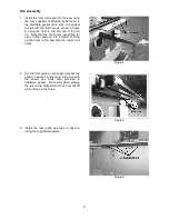
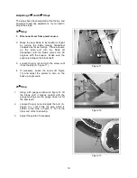
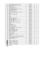
1. Place the fence on the rails and check for
alignment with the mitre guage slot as
shown in Figure 7.
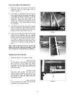
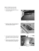
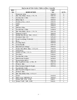
2. If the fence is not parallel to the mitre guage
slot, lift the fence off the guides and place it
on the table as shown in figure 8. Turn the
appropriate screw, B to compensate for the
difference. Place the fence back on the
guides and check again for alignment to the
mitre guage. If it is still mis-aligned, repeat
the procedure.
3. If the fence does not securely lock into place
with the lock handle, again adjust screws (B,
Figure 8) inward equal amounts to put more
pressure on the locking cam to the rail.
4. If the fence height with respect to the table
needs to be adjusted use the leveling
screws (A, Figure 8) in conjunction with the
leveling knob on the other end of the fence.
It is best to adjust the height as close a
possible to the table as long as it doesn’t rub
or bind up on anything as it travels along it’s
rails.
Note: Before leveling the fence, remove the
plastic screws (A, Figure 8) and apply a thin
coat of oil to the screws before re-installing.
Adjusting the Scale Reader
1. Raise the blade to it’s maximum height.
2.
Place the fence
on the guides on the right side of blade and
then slide the fence toward the blade.
Continue until the fence just touches the
saw teeth. Do not push too hard or the
blade will deflect.
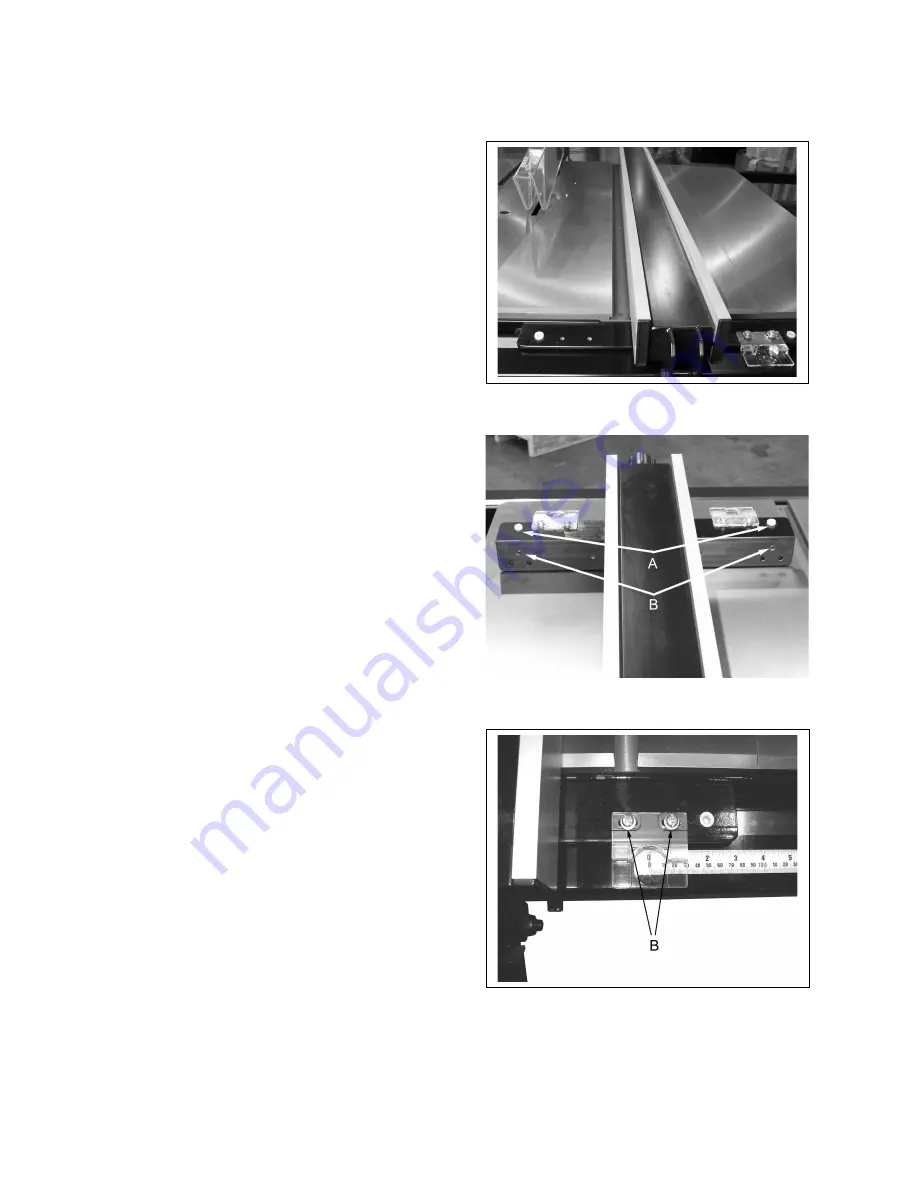
3.
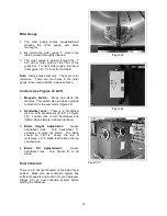
Looking at the
right side scale reader, the red pointer
should match up with the zero mark. If not,
loosen the two screws, B, Figure 9 and slide
the viewer to align the mark with zero.
Tighten the screws.
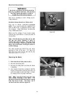
4.
Move the fence
to the left side of the blade and repeat the
procedure for the left side viewer.
Figure 7
Figure 8
Figure 9
9


