4430 Planer
OLIVERMACHINERY.NET
43
|
Page
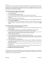
Adjust Cutterhead/Feed Roller Height Offset
The infeed/outfeed rollers pull the workpiece
through the planer. To ensure optimal
feeding/cutting performance, it is important to
ensure the height offsets between the
cutterhead and the feed rollers are correct.
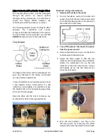
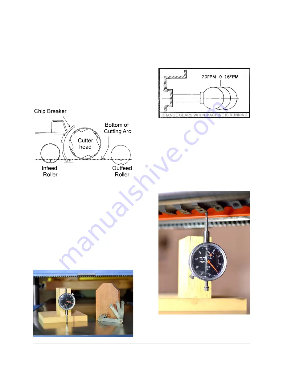
The following diagram shows the height offset
between
the
cutterhead
and
various
components inside the headstock of the planer.
The feed rollers and chip breaker are installed
BELOW
the lowest point of the cutterhead.
*Diagram not drawn to scale
The height of the rollers and the chip breaker has
been pre-calibrated in the factory and should
not need further adjustments.
In case if adjustments are needed, you will need
a dial indicator with a sturdy stand. If a dial
indicator is not available, it is possible to make
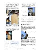
the adjustments with a homemade gauge block
and a set of feeler gauges.
Clean the table and the rollers to remove any
accumulations before making adjustments.
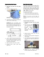
Method 1: Using a Dial Indicator
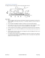
1.
Remove all tools from the planer.
2.
Turn on the planer, wait until it reaches full
speed, then shift the feed rate control knob
to 0 FPM (Neutral) position. This allows the
feed rollers to rotate freely.
3.
Turn off the planer.
Disconnect the planer
from the power source!!
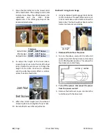
4.
Remove the belt cover so you can rotate the
cutterhead with the drive belt.
5.
Adjust the table height so that the dial
indicator can fit right below the cutterhead.
Rotate the cutterhead and use the dial
indicator to locate its lowest point. Using a
flat bottom tip for the dial indicator can
make this task easier.
6.
Zero the dial indicator. Use this as the
reference point for measuring the offset
between the cutterhead and the feed rollers.
Summary of Contents for 4430.201 M-4430
Page 2: ......
Page 10: ...10 Page Oliver Machinery 4430 Planer Identification...
Page 11: ...4430 Planer OLIVERMACHINERY NET 11 Page...
Page 12: ...12 Page Oliver Machinery 4430 Planer...
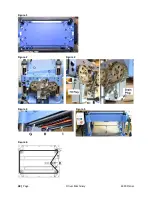
Page 38: ...38 Page Oliver Machinery 4430 Planer Figure 1 Figure 2 Figure 3 Figure 4 Figure 5 Figure 6...
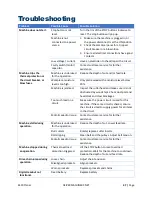
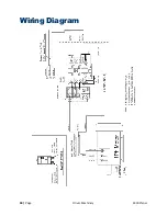
Page 50: ...50 Page Oliver Machinery 4430 Planer Wiring Diagram...
Page 51: ...4430 Planer OLIVERMACHINERY NET 51 Page Parts List Table Assembly...
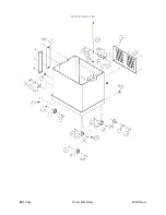
Page 52: ...52 Page Oliver Machinery 4430 Planer Cabinet Assembly...
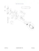
Page 53: ...4430 Planer OLIVERMACHINERY NET 53 Page Motor Mount Assembly...
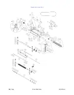
Page 54: ...54 Page Oliver Machinery 4430 Planer Headstock Assembly...
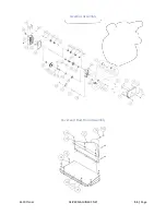
Page 55: ...4430 Planer OLIVERMACHINERY NET 55 Page Gearbox Assembly Cover and Dust Hood Assembly...
Page 62: ...62 Page Oliver Machinery 4430 Planer Maintenance Record Date Task Operator...
Page 63: ...4430 Planer OLIVERMACHINERY NET 63 Page Notes...

