d-Color MF4003/MF3303
P THEORY OF OPERATION > 8. FK-517
P-96
Signal Definition
Signal type
Meaning
Signal direction
Call Called
Signal
speed
Timing of transmission
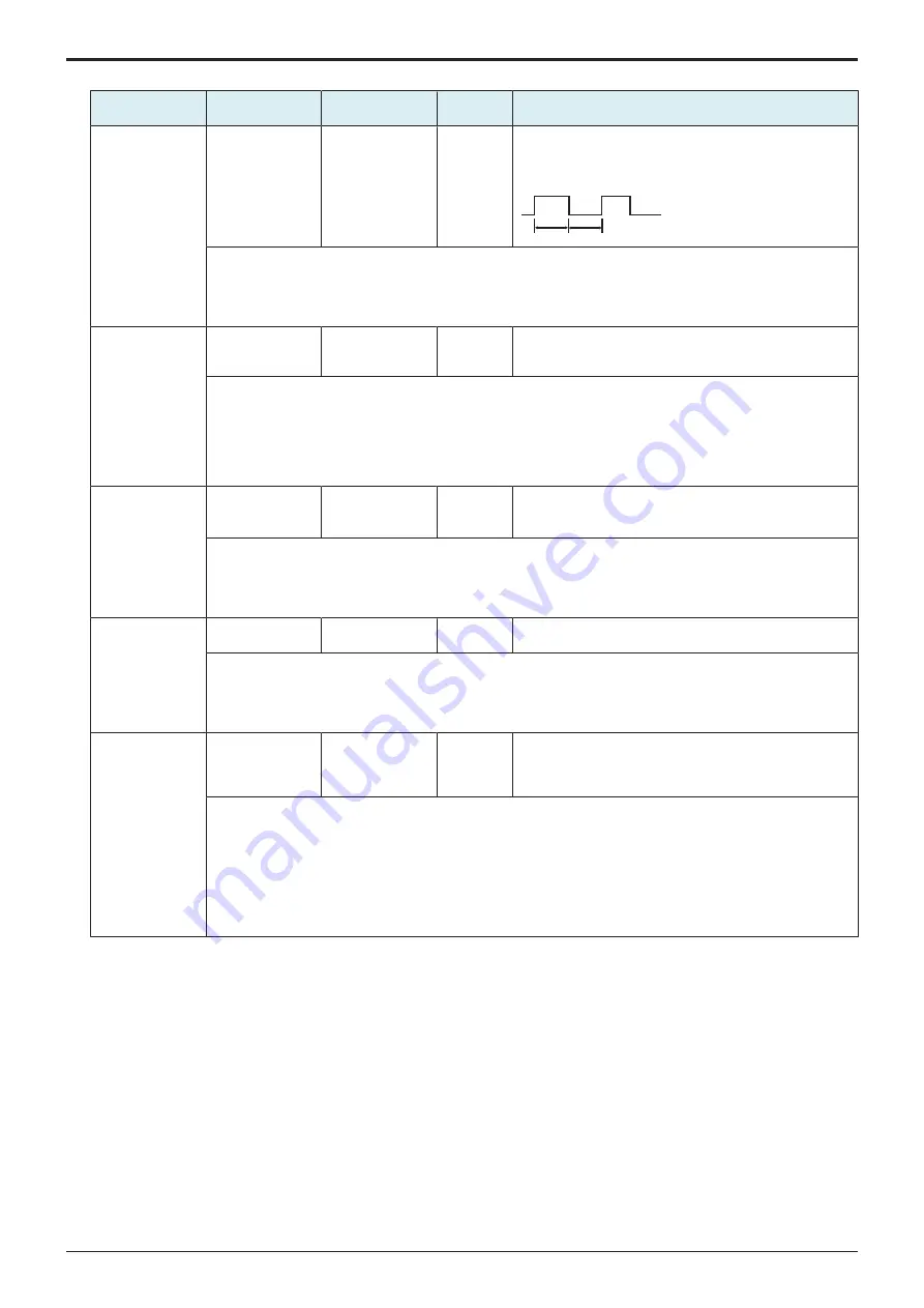
CI (Call Indicator)
Function display on
the calling side
->
V.21 (L)
(300 bps)
• Start: after 0.4 seconds after line connection from ON
condition (in the following format)
• Stop: when 3 period or more has passed after ANSam/
ANS is detected
ON
OFF
ON: 3period< T < 2sec
OFF: 0.4sec < T < 2sec
[Comments]
• CI is a signal to carry call function.
• The calling side send CI, CT (Call Tone - V25) or CNG.
• CI transmission and detection are optional.
• The ON minimum time (=3 Period) is of duration of three CI signals in the following format.
ANSam (Modified
Answer Tone)
V.8 procedure on
the called side
Support display
<-
-
When 0.2 seconds or more has passed after reception
[Comments]
• Essential for a called machine which supports the V8 procedure.
• 2100 Hz sine wave is phase-inverted by 400 +/-25 ms periods, then amplitude modulated by 15 +/-0.1 Hz sine
wave
• Average value of modulation factor (x) 0.8 +/- 0.01 < x < 1.2 +/- 0.01
• Average transmission power compliant to V2
• 2100 +/- 200 Hz external power is smaller than the average power by 24 dB or more.
CM (Call Menu)
Modulation mode
etc. on the calling
side
->
(300 bps)
V.21 (L)
• Start: Te (0.5 sec.
≤
Te
≤
1 sec.) has passed after CI
transmission stops
• Stop: When two or more JM are detected
[Comments]
• CM is a signal which carries call function, modulation modes, protocols and GSTN access.
• The first information category is call function.
• Protocols and GSTN access category are added when the calling side has ability and when needed to inform to
a remote station.
CJ
CM termination
->
(300 bps)
V.21 (L)
When CM is completed
[Comments]
• START bit (0) and STOP bit (1) are added to 1 octet of all bit 0.
• Signal format
0
0
0
0
0
0
0
0
0
1
Start bit
b0
Stop bit
b1
b2
b3
b4
b5
b6
b7
JM (Joint Menu)
Display of common
ability on both
calling and called
sides
<-
(300 bps)
V.21 (H)
• Start: When two or more same CM are received
• Stop: When CJ is received or receives a signal matching
the selected Modulation Mode from the calling side
[Comments]
• JM is a response signal to CM and of the same format as the received CM.
• The fist information category is Call Function as same as CM.
• Modulation mode sets the common bit on calling and called sides and sends by the same octet as received CM.
• When there is no common ability, all bits are set to 0 and send by the same octet as received CM.
• The minimum item No. is selected from the common bits to determine the actual Modulation Mode.
• Protocol is added when it is included in received CM and needed to instruct.
• GSTN access is added when it is included in received CM and needed to instruct.
• Bit 6 is set to ON when needed to show ability. Bit 5 is set to the same one as received CM.
Signal format
1.
Preamble: a signal added before each signal when CI, CM and JM signals are sent.
• Format: 11110000000001 (for CI)
• Format: 11110000001111 (for CM and JM)
2.
Common format among each signal CI, CM and JM
• Start Bit (=0) is put at the top and Stop Bit (=1) is put at the end of each octet.
Service Manual
Y119930-3
Summary of Contents for d-Color MF 4003
Page 1: ...Multifunction Digital Copier d Color MF4003 MF3303 Service Manual Version 2 0 Code Y119930 3 ...
Page 48: ...This page is intentionally left blank ...
Page 54: ...This page is intentionally left blank ...
Page 70: ...This page is intentionally left blank ...
Page 76: ...This page is intentionally left blank ...
Page 98: ...This page is intentionally left blank ...
Page 216: ...This page is intentionally left blank ...
Page 354: ...This page is intentionally left blank ...
Page 388: ...This page is intentionally left blank ...
Page 398: ...This page is intentionally left blank ...
Page 570: ...This page is intentionally left blank ...
Page 572: ...This page is intentionally left blank ...
Page 574: ...This page is intentionally left blank ...


