Fuser motor
(counterclockwise turn)
Output roller
(drive)
Heat roller (drive)
Fuser unit
Figure 2-7
Figure 2-8
Fuser motor
(clockwise turn)
Output roller
(stop)
Heat roller (stop)
Cover open gear
Fuser unit
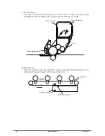
(5) Fusing Unit and Paper Output
1. As shown in Figure 2-7, the fuser unit and output roller are driven by the pulse motor.
When the fuser motor turns counterclockwise, the heat roller turns. This roller fuses the
toner image ‘on the paper with heat and pressure.
2. At the same time, the output roller turns and ‘sends out the paper.
(6) Cover Open Operation of Color Registration Sensor and Density Sensor
1. As shown in Figure 2-8, when the fuser motor turns clockwise, the cover open gear
also turns and the covers of the color registration sensor and the density sensor will
open.
2. When the fuser motor turns counterclockwise, interlocking of the cover open gear is
released and the covers of the color registration sensor and the density sensor will
close.
Y108500-4
Service Manual
25


