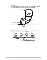
Shading board
Shutter
Toner sensor
(light reception sensor)
Luminous LED
Toner cartridge lever
Toner stir
Toner Sensor Detection Principle
Detection of the low toner is performed by the toner sensor (light reception sensor) installed
inside the equipment and the luminous LED installed inside the cartridge. The shading board is
installed inside the ID and rotates synchronizing with the toner stir. A shutter is attached to the
ID. The shutter synchronizes with the cartridge operation lever and the toner sensor can detect
whether the cartridge is installed properly. If the toner sensor is stained by the toner, etc., or the
ID unit and the toner sensor are not facing each other as specified due to improper setting of
the ID unit or for other reason, the detection may not be executed normally, resulting in a toner
sensor error.
Toner Counter Principle
After the image data is developed into 2 value data to enable printing using the MFP, the print
dot number is counted by the LSI. The amount of the toner used is counted from the above
count value and the remaining amount is displayed. On the other hand, detection of the low
toner by the toner sensor is physically made when the amount of the toner remaining in the
cartridge comes to be under certain amount.
Principles of ID, Belt and Fusing Counter
ID Counter
: 1 count is the value of one third of the amount of drum rotation when three
A4 sheets of paper are continuously printed.
Belt Counter :
1 count is one third of the amount of the belt rotation when three A4 sheets
of paper are continuously printed.
Fusing Counter: Standard is the length of Legal 13 inches sheet of paper. 1 count is the sheet
of paper under that length and when the length is more than that, the number
of count is decided by multiples of Legal 13 inches. (Number under the
decimal point is rounded up.)
30
Service Manual
Y108500-4


