background image

 =82SWLRQ

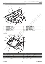
[1]

[2]

[3]

[4]

[5]

[6]

[7]

[8]

[9]

[10]

[11]

[13]

[12]

[14]

[15]

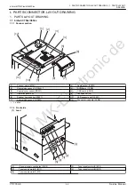
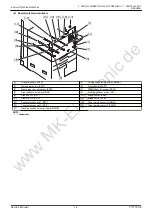
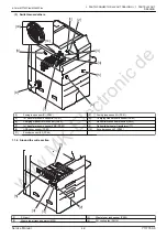
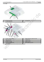
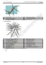
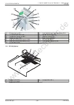
[1]

Main motor cooling fan (FM601)

[2]

Punch shift motor (M605)

[3]

Punch shift home sensor (PS605)

[4]

ZU control board (ZUCB)

[5]

Circuit breaker/2 (CBR2)

[6]

Circuit breaker/1 (CBR1)

[7]

Power relay (RY1)

[8]

Noise filter (NF1)

[9]

Coil (COIL)

[10]

DC power supply/1 (DCPU1)

[11]

Door switch (MS602)

[12]

DC power supply/2 (DCPU2)

[13]

Punch scraps box set sensor (PS607)

[14]

Punch scraps full sensor (PS608)

[15]

Punch scraps conveyance motor (M607)

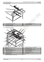
-

-

[4]

[3]

[2]

[1]

[11]

[10]

[9]

[5]

[6]

[7]

[8]

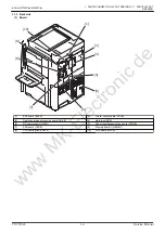
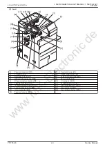
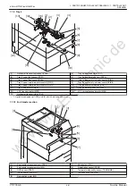
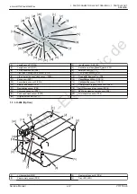
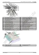
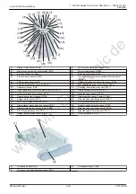
[1]

Main motor (M606)

[2]

Conveyance encoder sensor (PS610)

[3]

Gate solenoid/Lw (SD601)

[4]

Registration motor (M601)

[5]

2nd folding stopper home sensor (PS604)

[6]

Exit sensor (PS609)

[7]

2nd folding stopper motor (M603)

[8]

Gate solenoid/Up (SD602)

[9]

Conveyance sensor (PS601)

[10]

1st folding stopper motor (M602)

[11]

1st folding stopper home sensor (PS603)

-

-

d-Color MF752Plus/MF652Plus

L  PARTS/CONNECTOR LAYOUT DRAWING > 1.  PARTS LAYOUT

DRAWING

/

Service Manual

Y117760-6

www 

MK-Electronic 

de

Summary of Contents for d-color mf752plus

Page 1: ...SERVICE MANUAL Multifuction Digital Copier d Color MF752Plus MF652Plus and Options Code Y117760 6 w w w M K E l e c t r o n i c d e...

Page 2: ...panel unit 8 Fax speaker SP 9 Scanner home sensor PS201 10 LED exposure unit LA201 11 Original size sensor 1 PS203 12 Scanner drive board SCDB 1 option URQW VLGH RDG 1 2 3 4 5 1 IH power supply coolin...

Page 3: ...ottom door switch MS3 8 Front upper door switch RS1 9 Erase LED Y EL Y 10 Erase LED M EL M 11 Erase LED C EL C 12 Erase LED K EL K 13 Toner empty sensor Y RS Y 14 Toner empty sensor M RS M 15 Toner em...

Page 4: ...rd DSIPB 4 Hard disk HDD 5 DC power supply DCPU 6 Paper feed transport drive board PFTDB 7 SSD board SSDB 8 Memory board 1 MEMB 1 9 CPU cooling fan FM104 10 MFP board MFPB d Color MF752Plus MF652Plus...

Page 5: ...gh voltage unit 3 HV3 3 High voltage unit 1 HV1 4 Noise filter NF1 5 Dehumidifier relay board DEDB d Color MF752Plus MF652Plus L PARTS CONNECTOR LAYOUT DRAWING 1 PARTS LAYOUT DRAWING Service Manual Y1...

Page 6: ...power supply cooling fan FM9 10 IU cooling fan FM15 11 Cleaning brush motor M38 12 Developing motor YMC M17 13 1st transfer pressure motor M21 14 Toner cartridge motor YM M13 15 Toner cartridge motor...

Page 7: ...r switch SW2 7 1st transfer pressure sensor YMC PS52 8 Dehumidifier heater transformer T1 9 USB cover sensor PS60 10 Encoder sensor K1 PS45 11 Encoder sensor K2 PS46 URXQG WKH ZULWH VHFWLRQ 1 4 3 2 5...

Page 8: ...r limit sensor PS36 7UD 6 7 12 11 10 9 3 4 1 5 8 2 1 Tray 1 vertical transport motor M5 2 Tray 1 paper feed clutch CL1 3 Tray 1 upper limit sensor PS6 4 Tray 1 vertical transport sensor PS4 5 Tray 1 p...

Page 9: ...2 lift up motor M8 7UD 8 7 6 9 10 11 1 2 5 4 3 1 Tray 3 upper limit sensor PS22 2 Tray 3 paper empty sensor PS19 3 LCC vertical transport sensor PS28 4 Horizontal transport sensor PS29 5 Tray 3 paper...

Page 10: ...ft up motor M24 12 Tray 4 near empty sensor PS25 13 LCC transport motor M25 14 LCC vertical transport motor M26 15 Horizontal transport clutch CL3 1 Optional equipment HT 508 only for North America an...

Page 11: ...l FH1 4 Paper exit sensor PS39 5 Gate switch solenoid SD1 6 Heating roller rotation sensor PS56 7 Fusing pressure home sensor PS55 8 Tucking fan Fr FM103 1 9 Tucking fan Md FM101 1 10 Tucking fan Rr F...

Page 12: ...motor M6 3 Stamp solenoid SD1 4 Lift up motor M5 5 Take up clutch CL1 6 Take up motor M2 7 Registration motor M3 8 Reading motor M1 9 Take up motor cooling fan FM1 10 Back side cleaning motor M7 11 E...

Page 13: ...olidation sensor 2 PS14 14 Consolidation sensor 1 PS13 15 Before read sensor PS6 16 Different width registration sensor PS22 17 Registration sensor PS5 18 Left Cover open close sensor PS16 19 Conveyan...

Page 14: ...7 8 9 10 11 12 13 1 LU door switch MS1 2 Near empty sensor 2 PS6 3 Paper empty sensor PS4 4 Tray LED LED 5 Dehumidification heater DH 6 Paper feed sensor PS3 7 Upper limit sensor PS2 8 Tray set senso...

Page 15: ...607 14 Punch scraps full sensor PS608 15 Punch scraps conveyance motor M607 4 3 2 1 11 10 9 5 6 7 8 1 Main motor M606 2 Conveyance encoder sensor PS610 3 Gate solenoid Lw SD601 4 Registration motor M6...

Page 16: ...5 6 1st transport motor M1 7 Center staple switching gate solenoid SD1 8 Main tray up down motor M5 9 Bypass switching gate solenoid SD2 10 Stapler movement motor M13 11 Switchback gate solenoid SD4 1...

Page 17: ...S51 17 Trailing edge stopper home sensor PS22 18 Stapler position sensor 4 PS53 19 Stapler position sensor 3 PS52 20 Alignment plate motor home sensor Fr PS17 21 Main tray upper limit sensor in PS44 2...

Page 18: ...ole position sensor 2 PS301 6 2SWLRQ 1 2 3 5 6 7 8 9 10 11 4 1 Alignment motor M3 2 SD transport motor M1 3 Paper receiving guide control motor M2 4 Tri fold guide motor M6 5 Center fold change motor...

Page 19: ...sor PS6 9 SD exit full sensor PS35 10 SD exit tray lift sensor PS43 11 SD exit tray limit sensor PS41 12 SD exit sensor PS12 13 Center fold home sensor PS8 14 SD drive board SDDB 6 2SWLRQ 1 2 3 4 1 3r...

Page 20: ...et sensor Up PS203 18 L size sensor Lw PS212 19 Tray lift motor Lw M202 20 Tray lower limit sensor Lw PS210 21 Tray lower limit sensor Up PS205 22 Transfer motor M203 23 Tray lift motor Up M201 24 Tra...

Page 21: ...oor open detect switch SW1 17 Alignment plate F home sensor PS12 18 Main tray upper sensor in PS7 19 Paper delivery control sensor PS28 20 Stapler position sensor Center PS24 21 Gripper motor sensor P...

Page 22: ...9 7 1 Alignment motor M3 2 SD transport motor M1 3 Paper discharge control motor M2 4 Center fold guide motor M8 5 Tri folding guide motor M6 6 SD paddle motor M7 7 Stopper solenoid SD1 8 Stopper driv...

Page 23: ...sensor PS5 8 Stopper home sensor PS6 9 Booklet tray empty detection sensor out PS14 10 Fold exit sensor PS12 11 Booklet tray empty detection sensor in PS13 12 Center fold knife home sensor PS8 13 SD...

Page 24: ...CN n CN n CN n CN n CN n CN n CN n CN n CN n CN n CN n CN N C CN n CN n CN n CN n CN n CN n CN n CN n CN n CN n CN n CN n CN n CN n CN n CN n CN n CN n CN n CN n CN n CN n CN N C d Color MF752Plus MF...

Page 25: ...C PJ18 34pin PJ16 N C PJ05 N C PJ13 20pin PJ36 15pin PJ34 15pin 3DSHU IHHG WUDQVSRUW GULYH ERDUG 3 7 CN n CN n CN n CN n CN n CN n CN n CN n CN n CN n CN n CN n CN n CN n CN n CN n CN n CN n CN n CN...

Page 26: ...CN n CN n CN n CN n CN n CN n CN n CN n 6FDQQHU GULYH ERDUG 6 n n n n n n XDO VFDQ LPDJH SURFHVVLQJ ERDUG 6 3 n n d Color MF752Plus MF652Plus L PARTS CONNECTOR LAYOUT DRAWING 2 CONNECTOR LAYOUT DRAWI...

Page 27: ...CN n SRZHU VXSSO 38 CN n CN n CN n PDJQHWLF HUDVLQJ ERDUG 0 CN n CN n d Color MF752Plus MF652Plus L PARTS CONNECTOR LAYOUT DRAWING 2 CONNECTOR LAYOUT DRAWING Service Manual Y117760 6 w w w M K E l e...

Page 28: ...n CN n CN n CN n CN N C CN n CN n LJK YROWDJH XQLW 9 CN n CN n LJK YROWDJH XQLW 9 CN n d Color MF752Plus MF652Plus L PARTS CONNECTOR LAYOUT DRAWING 2 CONNECTOR LAYOUT DRAWING Y117760 6 Service Manual...

Page 29: ...LILHU UHOD ERDUG CN n CN n FRQWURO ERDUG 1 in in in in 1 in 2 in 2 1 in 1 2 in in 12 1 in 11 in 1 in 1 in 1 in in d Color MF752Plus MF652Plus L PARTS CONNECTOR LAYOUT DRAWING 2 CONNECTOR LAYOUT DRAWIN...

Page 30: ...RO ERDUG 3 3 CN34 6pin CN35 3pin CN32 8pin CN33 9pin CN37 6pin CN36 12pin CN38 11pin CN300 3pin CN301 9pin d Color MF752Plus MF652Plus L PARTS CONNECTOR LAYOUT DRAWING 2 CONNECTOR LAYOUT DRAWING Y1177...

Page 31: ...pin CN30 8pin CN21 14pin CN18 11pin CN61 16pin CN50 19pin CN24 20pin CN23 20pin CN19 15pin CN15 15pin CN14 14pin CN12 12pin CN11 12pin CN31 9pin CN1 2pin CN5 3pin CN4 6pin CN3 4pin CN2 15pin CN22 15pi...

Page 32: ...pin SW2 8pin SW1 10pin 58 FRQWURO ERDUG 58 6 2 2 in 2 in 1 1 1 in 2 1 in 2 2 2 in 2 in 2 in 6 GULYH ERDUG 6 6 J4 13pin J6 4pin J10 9pin J11 20pin J9 10pin J8 14pin J3 4pin J1 4pin J2 6pin J5 11pin J7...

Page 33: ...k Meaning of mark Number of pin Possible to confirm by removing external cover The number in the mark represents the number of pin of the relay connector Not possible to confirm by removing external c...

Page 34: ...CN334 6 I 5 CN322 7 J 6 CN198 7 R 7 CN172 9 S 8 CN195 B 11 S 9 CN202 9 B 10 CN385 1 E 11 CN706 20 J 12 CN267 20 J 13 CN707 7 B 14 CN142 9 S 15 CN428 3 I 16 CN330 3 I 17 CN306 12 I 18 CN320 3 J 19 CN1...

Page 35: ...8 CN131 9 W 9 CN121 A 7 V 10 CN121 B 8 V 11 CN194 8 W 12 CN123 7 W 13 CN122 7 W 14 CN129 7 W 15 CN134 7 W 16 CN119 6 W 17 CN118 5 W 18 CN113 A 5 V 19 CN193 6 W 20 CN113 B 6 V 21 CN143 9 W 22 CN197 10...

Page 36: ...11 20 D 4 CN241 21 E 5 CN165 10 J 6 CN228 20 E 7 CN702 6 J 8 CN378 10 J 9 CN235 17 E 10 CN242 17 E 11 CN333 19 J 12 CN199 8 R 13 CN329 18 I 14 CN253 22 E 15 CN328 2 J 16 CN381 22 J d Color MF752Plus M...

Page 37: ...1 2 S 4 CN279 6 R 5 CN613 19 I 6 CN278 6 Q 7 CN293 9 J 8 CN258 23 24 E 9 CN156 3 Q 10 CN195 A 10 S 11 CN151 2 Q 12 CN427 12 S 13 CN271 A 5 S 14 CN503 16 E 15 CN271 B 6 S 16 CN504 16 E d Color MF752Pl...

Reviews: