background image

27

4

8

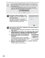
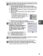
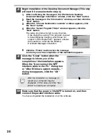
Begin installation of the Desktop Document Manager (This step 
will start if it was selected in step 4).

1

After confirming the message in the "Welcome to Desktop 
Document Manager installation" window, click the "Next" button.

2

Read the message in the "Information" window, and then click the 
"Next" button.

3

When the "Choose Destination Location" window appears, click 
the "Next" button.

4

When the "Select Program Folder" window appears, click the 
"Next" button.

The setup program will start to copy the files.

If the dialog box asking "This program is about 
to install Desktop Imaging, which does not 
support LZW compression." appears, answer 
the question to continue the Desktop 
Document Manager installation.

5

Click the "Finish" button when the message 
to inform you of the completion of the installation appears.

9

Click the "Close" button when the 
message to inform you of the 
completion of the installation appears. 
When the "Now connect the MFP 
interface cable to the PC." dialog box 
or "After Windows system restarts..." 
dialog box appears, click the "OK" 
button.

10

Make sure that the power of the MFP is turned on, and then
connect the USB interface cable. (p.45)

Windows will detect the MFP and the Plug and Play screen will appear. 

11

Follow the instructions in the Plug and Play screen that 
appears in your version of Windows to begin the installation.

You have completed the installation of the software.

After the installation, a message to 
restart your computer may be 
displayed. In this case, click the "Yes" 
button to restart your computer.

Desktop Imaging Setup 


Desktop  Imaging,

Desktop Document Manager

Summary of Contents for d-Copia 150

Page 1: ......

Page 2: ...UBLICATION ISSUED BY Olivetti Tecnost S p A Divisione Business Prodotti Office Via Jervis 77 10015 Ivrea TO www olivettitecnost com Copyright 2003 Olivetti Tutti i diritti riservati All rights reserve...

Page 3: ...is on Doing so may prevent heat radiation damaging the unit Use of controls or adjustments or performance of procedures other than those specified herein may result in hazardous radiation exposure The...

Page 4: ...the property of their respective owners Cautions on laser In some areas the POWER switch positions are marked I and O on the copier instead of ON and OFF The symbol O denotes the copier is not comple...

Page 5: ...31 USING THE PRINTER MODE 32 USING THE SCANNER MODE 34 HOW TO USE THE ONLINE MANUAL 43 USING OTHER INSTALLED DRIVERS 44 CONNECTING THE INTERFACE CABLE 45 5 MAKING COPIES SCAN ONCE PRINT MANY 46 COPY F...

Page 6: ...how to solve driver or software problems Conventions used in this manual and online manual This operation manual explains the operation of models with and without the SPF In cases where the operation...

Page 7: ...cover Paper tray Side cover Side cover open button Bypass paper guides Paper output tray Paper output tray extension 1 2 3 4 5 6 7 8 9 Power switch Handle Power cord socket Fusing unit release lever...

Page 8: ...ecified copy quantity zoom copy ratio user program code and error code SCANNER key and indicator p 31 p 38 ON LINE key and indicator Lights up when the unit is used as a printer and scanner For descri...

Page 9: ...function cannot be used see TROUBLESHOOTING THE UNIT p 59 1 Open the package and make sure that all the accessories are supplied with the unit p 8 2 Remove the protective materials p 9 8 Now you can c...

Page 10: ...mponents and accessories are included If anything is not included or is damaged contact your authorized Service representative PREPARING THE UNIT FOR INSTALLATION 1 Be sure to hold the handles on both...

Page 11: ...protective materials After that take out the bag containing the power cord and TD cartridge SCAN HEAD LOCKING SWITCH The scan head locking switch is under the original table If the switch is locked th...

Page 12: ...e strings upward one at a time 3 Push gently on both sides of the front cover to open the cover 4 Remove the TD cartridge from the bag Remove the protective paper Hold the cartridge on both sides and...

Page 13: ...r and then the side cover by pressing the round projections near the side cover open button The indicator will go out and the start indicator will light up When closing the covers be sure to close the...

Page 14: ...djusts the scan head lamp periodically to maintain copying quality At this time the scan head moves automatically This is normal and does not indicate unit trouble If you use the unit in a country oth...

Page 15: ...anel are shown below When copying is begun in this state the settings in the following table are used Power off methods If not used for a certain period of time the unit will automatically enter auto...

Page 16: ...use physical damage to the unit For paper weighing from 104 to 128g m2 A4 is the maximum size that can be fed through the single bypass Special papers such as transparency film labels and envelope mus...

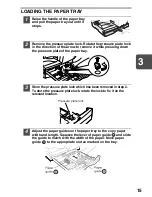
Page 17: ...pressure plate of the paper tray 3 Store the pressure plate lock which has been removed in step 2 To store the pressure plate lock rotate the lock to fix it on the relevant location 4 Adjust the pape...

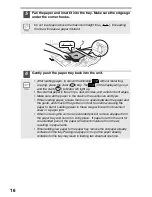
Page 18: ...n the stack is the same size and type When loading paper ensure there is no space between the paper and the guide and check if the guide is not set too narrow causing the paper to bend Loading paper i...

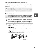
Page 19: ...sert a single sheet of copy or print paper print face down into the feed slot of the single bypass Using copy mode When you insert the paper the machine will automatically draw in the paper and begin...

Page 20: ...ce is not flat because of embossing may cause the prints to become smudged Under high humidity and temperature conditions the glue flaps on some envelopes may become sticky and be sealed closed when p...

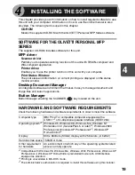
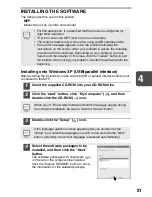
Page 21: ...applications Button Manager Button Manager enabling the SCANNER key located on the unit HARDWARE AND SOFTWARE REQUIREMENTS Check the following hardware and software requirements in order to install th...

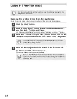
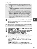
Page 22: ...you are using some of your computer s memory as a RAM drive the printer driver may not be allocated the correct amount of memory In such a case reduce the size of your RAM disk or do not use the RAM d...

Page 23: ...cription it is assumed that the mouse is configured for right hand operation To print or scan the MFP must be in the online state The scanner feature only works when using a USB interface cable If any...

Page 24: ...nected and click the Next button 3 Click the Next button in the dialog box to install the MFP driver or Cancel to quit the installation The setup program will start to copy the files If the following...

Page 25: ...aller will start 8 Begin installation of the Desktop Document Manager This step will start if it was selected in step 4 1 After confirming the message in the Welcome to Desktop Document Manager instal...
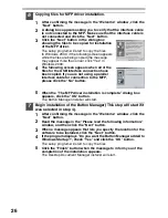
Page 26: ...box will appear Click the Continue Anyway button 3 When installation of the driver is completed click the Finish button to finish the scanner driver installation 12 Begin installation of the printer d...

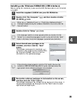
Page 27: ...to be installed on the screen and then click the Start button The software packages to be installed will be displayed on the screen If inappropriate packages are displayed click the Back button to sel...

Page 28: ...llel interface cable for connection to the MFP please click the No button 5 When the The MFP driver installation is complete dialog box appears click the OK button The Button Manager installer will st...

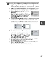
Page 29: ...ion 5 Click the Finish button when the message to inform you of the completion of the installation appears 9 Click the Close button when the message to inform you of the completion of the installation...

Page 30: ...d click OK 6 Check the contents of the package on the screen and then click the Start button The software packages to be installed will be displayed on the screen If inappropriate packages are display...

Page 31: ...odel number that is the same as the model name of your MFP and click the Next button Be sure to select the displayed model number that is the same as the MFP s model name If they are not the same the...

Page 32: ...compression appears answer the question to continue the Desktop Document Manager installation 5 Click the Finish button when the message to inform you of the completion of the installation appears 9...

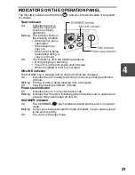
Page 33: ...mode When a misfeed or error has occurred ON LINE indicator The ON LINE key is pressed and on line and off line are changed On Indicates the unit is ready for printing or scanning is being performed O...

Page 34: ...i d Copia 150 printer driver icon in the Printers window and from the File menu select Properties 4 Click the Printing Preferences button in the General tab On Windows 95 98 Me click the Setup tab The...

Page 35: ...n indicator for the single bypass illuminates and insert the paper The machine will automatically draw in the paper and begin printing If copying is being performed when printing is started copying wi...

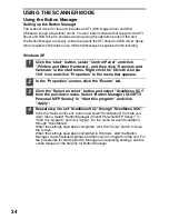
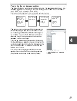
Page 36: ...click Properties in the menu that appears 2 In the Properties screen click the Events tab 3 Click the Select an event button and select ScanMenu SC1 from the pull down menu Select Button Manager OLIVE...

Page 37: ...sonal MFP Series in Start this program and click Apply Do the same for each ScanMenu through Scanmenu SC6 When the settings have been completed click the OK button to close the screen When the setting...

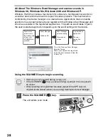
Page 38: ...ttings in Button Manager see the online manual or the help file This is the corresponding setting in the Button Manager to automatically send multiple images from the SPF in full colour at 75 dpi to D...

Page 39: ...tion that can be selected in Button Manager This can be done with the Windows OS showing the Event Manager selection dialog or directly into a selected application if the Button Manager is the only al...

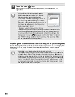
Page 40: ...for the device Using the SCANNER key to begin scanning 1 Press the SCANNER key The unit enters scan mode Scanning is not possible during a copy job If the SCANNER key is pressed during a print job th...

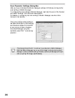
Page 41: ...are initially as follows To check the settings see Scan Parameter Setting Dialog Box p 36 and then open the settings window of the Button Manager Application number Application launched SC1 Desktop D...

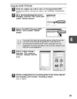
Page 42: ...ckbox selected in the Scan Parameter Setting Dialog Box p 36 the TWAIN settings screen p 41 will automatically appear Check the settings and then press the start key again or click the Scan button in...

Page 43: ...the Acquire button 5 Set the configuration for scanning refer to the online manual and help file and click the Scanning button Scan is started If you use more than one scanning device select the scan...

Page 44: ...scanning For information on the settings see the Windows XP help file After completing each setting click Next 3 Select a name format and folder for the scanned image For information on the image nam...

Page 45: ...lish folder and then the 5 d Copia 120 150 Setup EN pdf icon The following window will appear 6 Click the to read the online manual To close the online manual click the button located at the top right...

Page 46: ...and then click Properties 4 Click the Port tab Details tab on Windows 95 98 Me in the Properties dialog box select FILE in the Print to the following port list box and click the OK 5 Right click the i...

Page 47: ...erface cable 2 Ensure that your computer and unit are turned off 3 Insert the cable into the parallel interface connector located on the rear of the unit and fasten with clasps 4 Insert the other end...

Page 48: ...re using the single bypass check the paper size and then proceed to the next step without loading paper 2 Place the original If you are using the original table see Using the original table p 47 If yo...

Page 49: ...ce down on the original table Align it with the original scale and the centering mark Gently close the original cover SPF Do not insert paper in the single bypass when a copy job from the paper tray i...

Page 50: ...ely after completion of a copy run from the SPF The default setting of the stream feeding mode is ON See USER PROGRAMS p 53 Before feeding originals in the original feeder tray be sure to remove any s...

Page 51: ...adjust the copy density manually or to copy photographs the exposure level can be adjusted in five steps manually 1 Press the exposure mode selector key to select the manual mode or photo mode 2 Use...

Page 52: ...nd hold down the exposure mode selector key for approximately 5 seconds The photo indicator will go out and the AUTO indicator will begin to blink One or two exposure indicators corresponding to the a...

Page 53: ...a zoom or key is pressed the Zoom indicator will light up and the zoom ratio will be displayed in the display To verify a zoom setting without changing the zoom ratio press and hold down the copy rat...

Page 54: ...When the unit enters the auto power shut off mode the power save indicator will light up and other indicators will go out The auto power shut off mode saves more power than the preheat mode but requir...

Page 55: ...clear time stream feeding mode and resolution of AUTO MANUAL mode 1 Press and hold down the light and dark keys simultaneously for more than 5 seconds until all the alarm indicators blink and appears...

Page 56: ...ey for approximately 5 seconds The total number of copies will appear in two steps each with three digits Example Total number of copies is 1 234 Program No Mode Parameters 1 Auto clear time 0 OFF 1 1...

Page 57: ...lock release button 3 Install a new TD cartridge To install the new cartridge see INSTALLING THE TD CARTRIDGE p 10 Be sure to use only genuine Olivetti parts and supplies After the unit stops it may...

Page 58: ...ge at this time 1 Remove the TD cartridge see TD CARTRIDGE REPLACEMENT p 55 2 Hold the drum cartridge handle and gently pull the cartridge out Dispose of the old drum cartridge in accordance with loca...

Page 59: ...the back side of the original cover SPF Stains on the glass scanning window cover or SPF roller will also be copied Wipe the glass scanning window cover and SPF roller with a soft clean cloth If neces...

Page 60: ...charger cleaner onto the right end of the transfer charger gently slide the cleaner to the left end and then remove it Repeat this operation two or three times 4 Return the charger cleaner to its ori...

Page 61: ...unit in the automatic exposure mode Adjust the automatic exposure level 50 Is the unit in the photo exposure mode Cancel the photo exposure mode 49 Dust dirt smudges appear on copies Original table or...

Page 62: ...e SPF 64 Power save indicator is steadily lit The unit is in the preheat mode Press any key to cancel the preheat mode 52 The unit is in the auto power shut off mode Press the start key to cancel the...

Page 63: ...e SPF misfeeds an original sheet the unit will stop and the SPF misfeed indicator will blink while the misfeed indicator will remain off For a misfeed of originals in the SPF see D Misfeed in the SPF...

Page 64: ...projections near the side cover open button The misfeed indicator will go out and the start indicator will light up B Misfeed in the fusing area 1 Lower the fusing unit release lever The fusing unit i...

Page 65: ...feed in the fusing area p 62 2 Open the front cover To open the front cover see INSTALLING THE TD CARTRIDGE p 10 3 Rotate the feeding roller in the direction of the arrow and gently remove the misfed...

Page 66: ...feeder tray B in the exit area or C under the feeding roller Remove the misfed original following the instructions for each location A Open the feeding roller cover and pull the original gently to the...

Page 67: ...nto the exit area remove it in the direction of the arrow while rotating the knob A number may appear in the display after a minus sign indicating the number of the originals that must be returned to...

Page 68: ...in 15 pages min Print speed Max 12 pages min A4 Continuous copying printing Max 99 pages subtractive counter First copy print time Approximately 9 6 seconds 2 paper A4 exposure mode AUTO copy ratio 10...

Page 69: ...nditions Temperature 10 C to 30 C Humidity 20 to 85 Emulation GDI Interface IEEE1284 compliant bi directional parallel interface USB interface USB1 1 Standard Noise level Sound Power Level LwA 1B 10dB...

Page 70: ...ted pair cable USB 1 0 compatible 2m Max Be sure to use only genuine OLIVETTI parts and supplies For best copying results be sure to use only OLIVETTI Genuine Supplies which are designed engineered an...

Page 71: ...been stored in the front of the paper tray 5 Push the paper tray back into the unit 6 Lock the scan head locking switch p 9 7 Close the paper output tray extension and attach the packing materials and...

Page 72: ...py quantity 49 Copy quantity key 6 49 53 Copy ratio display key 6 51 Copy ratio selector indicators 6 51 Copy ratio selector key 6 51 D Dark key 6 49 Desktop Document Manager 19 Display 6 Displaying t...
Page 73: ...hoto copying 49 Power cord 5 Power off 13 Power on 12 Power save indicator 6 31 Power switch 5 12 Preheat mode 52 Preparing the unit for installation 8 Printer driver 19 Proper storage 69 R Reduction...

Page 74: ...esktop Document Manager 19 Installing the TD cartridge 10 Loading paper Paper tray 15 Single bypass 18 Loading the original Original table 47 SPF 48 Moving the unit 69 Opening the printer driver 32 Po...
Page 75: ...to another or over a network 3 Termination This license is effective until terminated You may terminate this License at any time by destroying the Software and related documentation and all copies th...

Page 76: ...ORAL OR WRITTEN INFORMATION OR ADVICE GIVEN BY OLIVETTI OR A OLIVETTI AUTHORIZED REPRESENTATIVE SHALL CREATE A WARRANTY OR IN ANY WAY INCREASE THE SCOPE OF THIS WARRANTY SHOULD THE SOFTWARE PROVE DEFE...

Page 77: ......

Page 78: ...Code 506604C 01 ENG...

Reviews: