2KL/2KK
1-5-53
1-5-8 Others
(1) Detaching and refitting the eject unit
Follow the procedure below to replace the eject unit.
Procedure
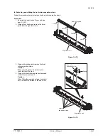
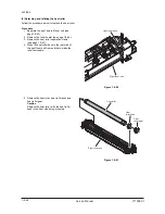
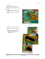
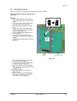
1. Remove the rear cover (see page 1-5-6).
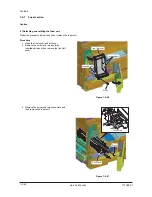
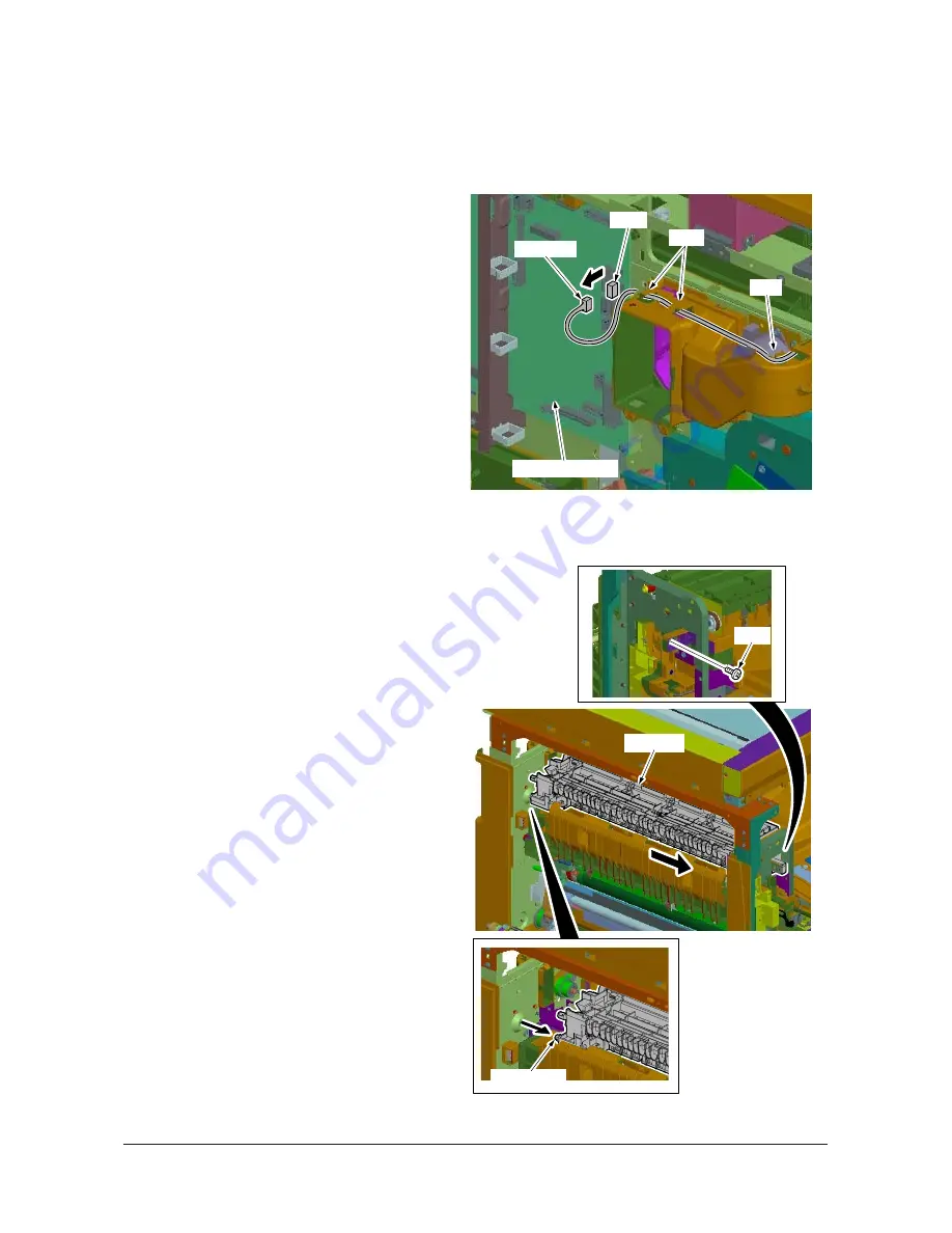
2. Remove YC14 connector of the main/engine
PWB.
3. Remove the wire of the connector from the
ribs.
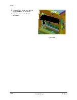
Figure 1-5-88
4. Remove the front left cover (see page 1-5-
40).
5. Remove the left middle cover (see page 1-5-
19).
6. Remove the eject cover (see page 1-5-30).
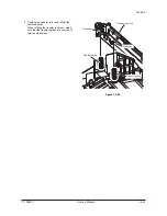
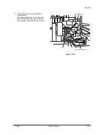
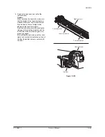
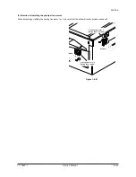
7. Remove the screw. Slide the eject unit
toward the front side and pull out the
inserted part section.
Figure 1-5-89
Main/engine PWB
YC14
Ribs
Rib
Connector
Screw
Eject unit
Inserted part
Y110980-1 Service Manual
Summary of Contents for d-Copia 1800
Page 1: ...d Copia 1800 d Copia 2200 Digital Copier SERVICE MANUAL Code Y110980 1...
Page 4: ...This page is intentionally left blank...
Page 10: ...This page is intentionally left blank...
Page 14: ...2KL 2KK This page is intentionally left blank...
Page 20: ...2KL 2KK 1 1 6 This page is intentionally left blank Service Manual Y110980 1...
Page 38: ...2KL 2KK 1 2 18 This page is intentionally left blank Service Manual Y110980 1...
Page 108: ...2KL 2KK 1 3 70 This page is intentionally left blank Service Manual Y110980 1...
Page 142: ...2KL 2KK 1 4 34 This page is intentionally left blank Service Manual Y110980 1...
Page 198: ...2KL 2KK 1 5 56 This page is intentionally left blank Service Manual Y110980 1...
Page 224: ...2KL 2KK 2 2 6 This page is intentionally left blank Service Manual Y110980 1...
Page 240: ...2KL 2KK 2 3 16 This page is intentionally left blank Service Manual Y110980 1...
Page 271: ...INSTALLATION GUIDE FOR PAPER FEEDER...
Page 285: ...INSTALLATION GUIDE FOR DUPLEX UNIT...
Page 294: ...INSTALLATION GUIDE FOR Printing System Z...
Page 297: ...UPDATING STATUS DATE UPDATED PAGES PAGES CODE 09 2009 1ST EDITION 297 Y110980 1...

