2-2-15
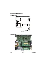
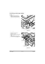
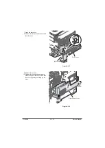
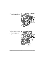
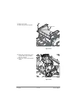
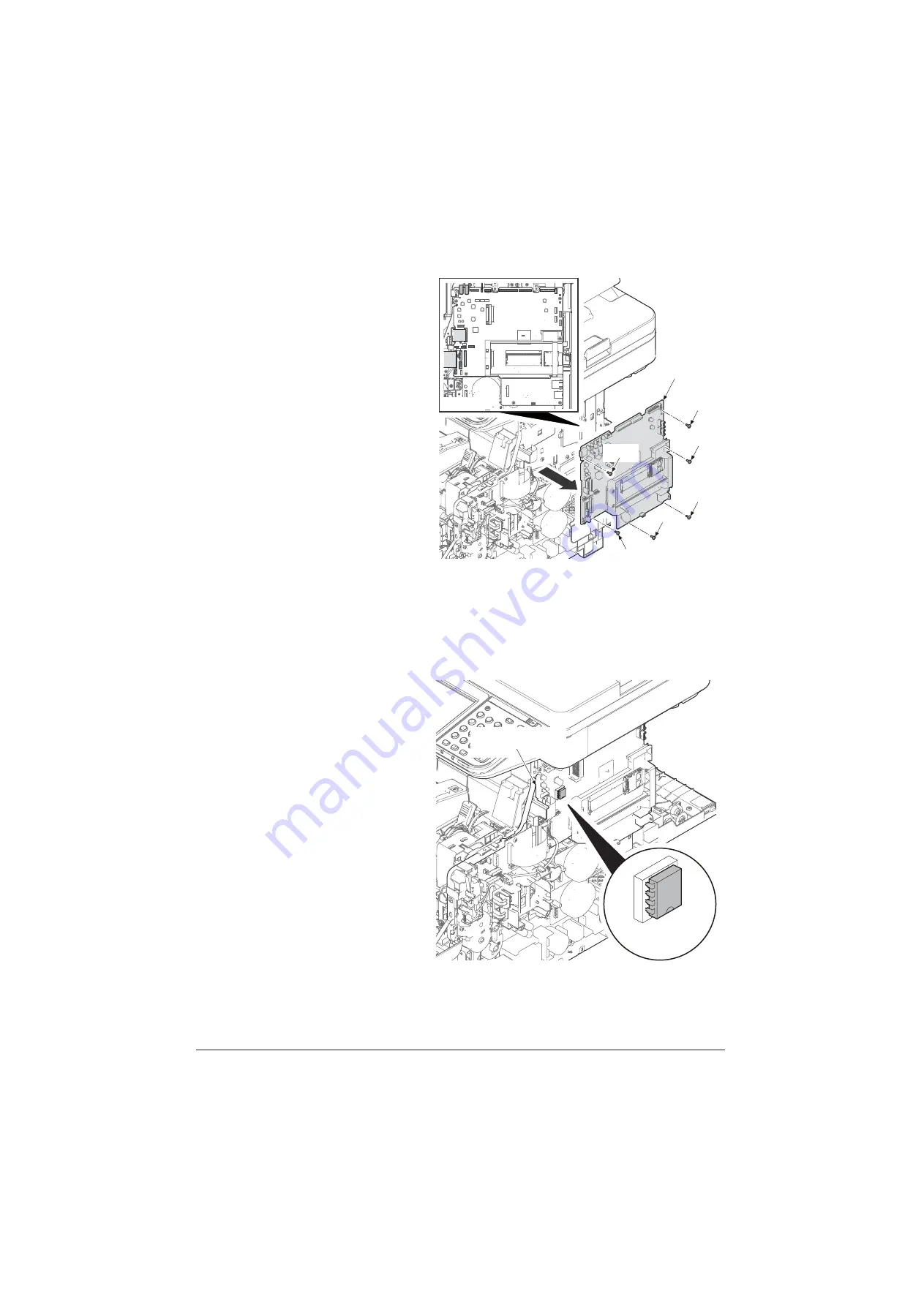
16. Remove all connectors and FFCs from
the control PWB.
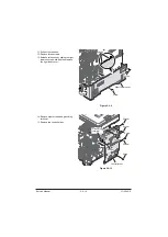
17. Remove six screws and control PWB
from the main unit.
18. Check or replace the control PWB and
refit all the removed parts.
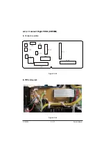
Figure 2-2-11
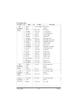
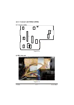
(5) Remarks on Control PWB replacement
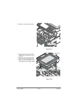
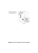
NOTE:
When replacing the PWB, remove the
EEPROM (U14) from the control PWB and
then reattach it to the new PWB.
Figure 2-2-12
Screw
Control PWB
Screw
Screw
Screw
Screw
Screw
Connector
EEPROM (U14)
Control PWB
Service Manual
Y116
540-5
Summary of Contents for d-Copia 4003MF
Page 11: ...This page is intentionally left blank...
Page 52: ...1 2 24 This page is intentionally left blank Service Manual Y116540 5...
Page 384: ...1 5 100 This page is intentionally left blank Service Manual Y116540 5...
Page 484: ...Installation Guide PF 320 Paper Feeder Installation Guide...
Page 486: ...For Legal Folio OficioII 1 1 1 1 2 2 2 2...
Page 487: ...UPDATINGSTATUS DATE UPDATEDPAGES PAGES CODE 03 2015 1ST EDITION 487 Y116540 5...

