11-12
687200Q
11.3.5 One Way Clutch Assemblies A & B (26T)/Envelope Feeder
Solenoid(29T)/Transfer Clutch Assembly (25T)/Torque Clutch
Assembly
Removal
NOTE: Since the gears are greased, take care that the grease does not stick to your hands. If grease
sticks to your hands, wipe it off completely with a paper towel to prevent grease contamination of
other parts.
1. Remove the Bottom Cover (
REP 11.3.3 Bottom Cover/Tray Extension).
2. Remove the Side Cover (
REP 11.3.4 Side Cover).
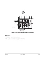
3. Lift off the One Way Clutch Assembly A (26T) {Clutch and Gear} while holding the roll on the Feeder
Roll Assembly (See (1) in Figure 11.3.5.1).
4. Lift off the One Way Clutch Assembly B (26T) {Clutch and Gear} while holding the roll on the Feeder
Roll Assembly (See (2) in Figure 11.3.5.1).
5. Lift off the Transfer Clutch Assembly (25T) (See (3) in Figure 11.3.5.1).
6. Remove the Envelope Feeder Solenoid Bearing on the Envelope Feeder Solenoid (29T) (See (4) in
Figure 11.3.5.1).
NOTE: Be careful not to forget to reinstall the Envelope Feeder Solenoid Bearing when reinstalling the
Envelope Feeder Solenoid.
7. Disconnect J230 of the Envelope Harness Assembly from the Envelope Feeder Solenoid (29T) (See
(5) in Figure 11.3.5.1).
8. Lift off the Envelope Feeder Solenoid (29T) together with the Envelope Feeder Solenoid Shaft (See
(6) in Figure 11.3.5.1).
NOTE: The Feeder Bearing can sometimes come off along with the Envelope Feeder Solenoid Shaft.
Take care not to loose the Feeder Bearing (See (7) in Figure 11.3.5.1).
9. Separate the Torque Clutch Assembly Shaft (17T) from the Torque Clutch Assembly (See (6) in Fig-
ure 11.3.5.1).
10. Remove the KL Ring (See (8) in Figure 11.3.5.1).
11. Lift off the Retard Link (See (9) in Figure 11.3.5.1).
NOTE: Be careful when replacing the Retard Link, it must be installed with the top side up. Install the
Retard Link with the locating tab facing upward.
12. Lift off the Torque Clutch Assembly (See (10) in Figure 11.3.5.1).
13. Lift off the One Way Clutch Assembly (26T) (See (11) in Figure 11.3.5.1) while holding the Retard
Roll Assembly Shaft (See (12) in Figure 11.3.5.1)
NOTE: Be careful when reinstalling the One Way Clutch Assembly insure that the gear is oriented on the
bottom.
Summary of Contents for DR N17
Page 1: ...DVHU 3ULQWHU 3 1 6HUYLFH 0DQXDO Code 687200Q 00 September 1999...
Page 3: ......
Page 6: ...iv 687200Q 1 2...
Page 8: ...vi 687200Q This page intentionally blank...
Page 12: ...687200Q Service Manual 1 2...
Page 16: ...2 2 687200Q...
Page 24: ...3 2 687200Q...
Page 26: ...3 4 687200Q PL 1 Covers I S S 2 1 S S 6 S KL S 3 5 S S S 4 S S SAS301FA...
Page 28: ...3 6 687200Q PL2 Covers II wsm3 07 7 8 13 4 3 2 5 9 11 S 1 with 2 11 12 6 10 SAS302FE...
Page 30: ...3 8 687200Q PL 3 Paper Tray 3 2 7 6 5 4 8 S S S 1 with 2 S S SAS303FB...
Page 32: ...3 10 687200Q PL 4 Paper Transportation I...
Page 36: ...3 14 687200Q PL 6 Paper Transportation III 2 S S S S 1 1 with 2 S SAS306FC...
Page 44: ...3 22 687200Q PL 10 Electrical Module I with Top Cover 2 4 3 S S 1 SAS310FB 5...
Page 48: ...3 26 687200Q 3 2 6 4 5 1 PL 12 System Controller...
Page 54: ...4 4 687200Q...
Page 190: ...5 78 687200Q This page intentionally left...
Page 193: ...687200Q Service Manual 5 81 Figure 5 5 1 2 Printer Data Label and Serial Number Plate...
Page 196: ...6 2 687200Q...
Page 206: ...6 12 687200Q This page intentionally blank...
Page 210: ...6 16 687200Q This page intentionally blank...
Page 243: ...687200Q Service Manual 6 49 This page intentionally blank...
Page 248: ...6 54 687200Q Notes...
Page 252: ...7 4 687200Q...
Page 262: ...7 14 687200Q This page intentionally blank...
Page 366: ...8 4 687200Q Figure 8 1 1 1 2 Paper Tray SAS214F...
Page 369: ...687200Q Service Manual 8 7 Figure 8 1 3 1 2 Tray W D H SAS217F...
Page 421: ...687200Q Service Manual 9 21 Replacement Perform the removal steps in reverse order...
Page 447: ...687200Q Service Manual 10 5 This page intentionally blank...
Page 476: ...10 34 687200Q Notes...
Page 492: ...11 16 687200Q Figure 11 3 7 1 Top Cover Removal FRONT 1 2 3 4 J230 J230 J231 J231 SAS4CAFA...
Page 518: ...Spare parts catalogue 687200Q DP N17 WITH OPTION SPARE PARTS CATALOGUE FROM SERVICE MANUAL 1...
Page 521: ...3 4 687200Q PL 1 Covers I S S 2 1 S S 6 S KL S 3 5 S S S 4 S S SAS301FA...
Page 523: ...3 6 687200Q PL2 Covers II wsm3 07 7 8 13 4 3 2 5 9 11 S 1 with 2 11 12 6 10 SAS302FE...
Page 525: ...3 8 687200Q PL 3 Paper Tray 3 2 7 6 5 4 8 S S S 1 with 2 S S SAS303FB...
Page 527: ...3 10 687200Q PL 4 Paper Transportation I...
Page 531: ...3 14 687200Q PL 6 Paper Transportation III 2 S S S S 1 1 with 2 S SAS306FC...
Page 539: ...3 22 687200Q PL 10 Electrical Module I with Top Cover 2 4 3 S S 1 SAS310FB 5...
Page 543: ...3 26 687200Q 3 2 6 4 5 1 PL 12 System Controller...
Page 555: ......
Page 556: ...Spare parts catalogue 687200Q A 1 GENERAL CODES INDEX DP N17...


