Field Service Ver. 3.0 Jan. 200
9
. Mechanical adjustment
77
FS-519/PK-515/OT
-602
Adjustment / Setting
9
.
Mechanical adjustment
9
.1
Punch
H
ole
D
evice
A
djustment (PK-5
10 / PK-515
)
NOTE
Make this adjustment after any of the following procedures has been performed.
• When the punch kit has been replaced.
• When the punch kit has been removed.
1.
Set the copier into the hole punch
mode and make a 1-sided copy from
a 1-sided original.
2.
Fold the output paper in half and
check whether the punch hole posi-
tions are aligned.
Specification: 0 ± 2 mm
3.
If the punch hole position is mis-
aligned, adjust with the following pro-
cedure.
4.
Remove the finisher unit right front cover.
See P.2
6
5.
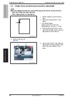
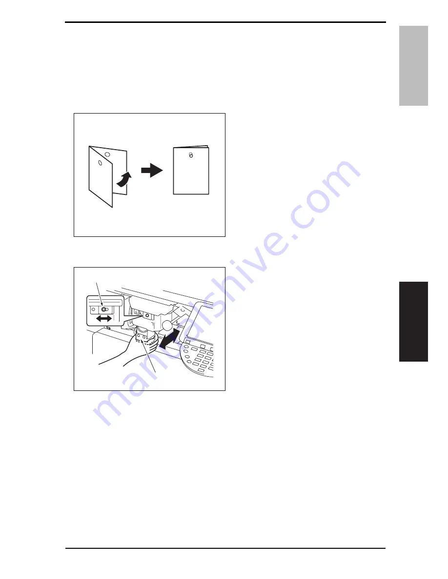
Loosen the adjustment screw [1],
and move the punch unit [2] forward
or backward to make the adjustment.
6.
After the adjustment has been com-
pleted, tighten the adjusting screw.
7.
Make a copy and check the punch
hole positions again.
4349F3C508DA
A01GF2C518DA
[2]
[1]
Y10
8442-7
Service Manual


