background image

7

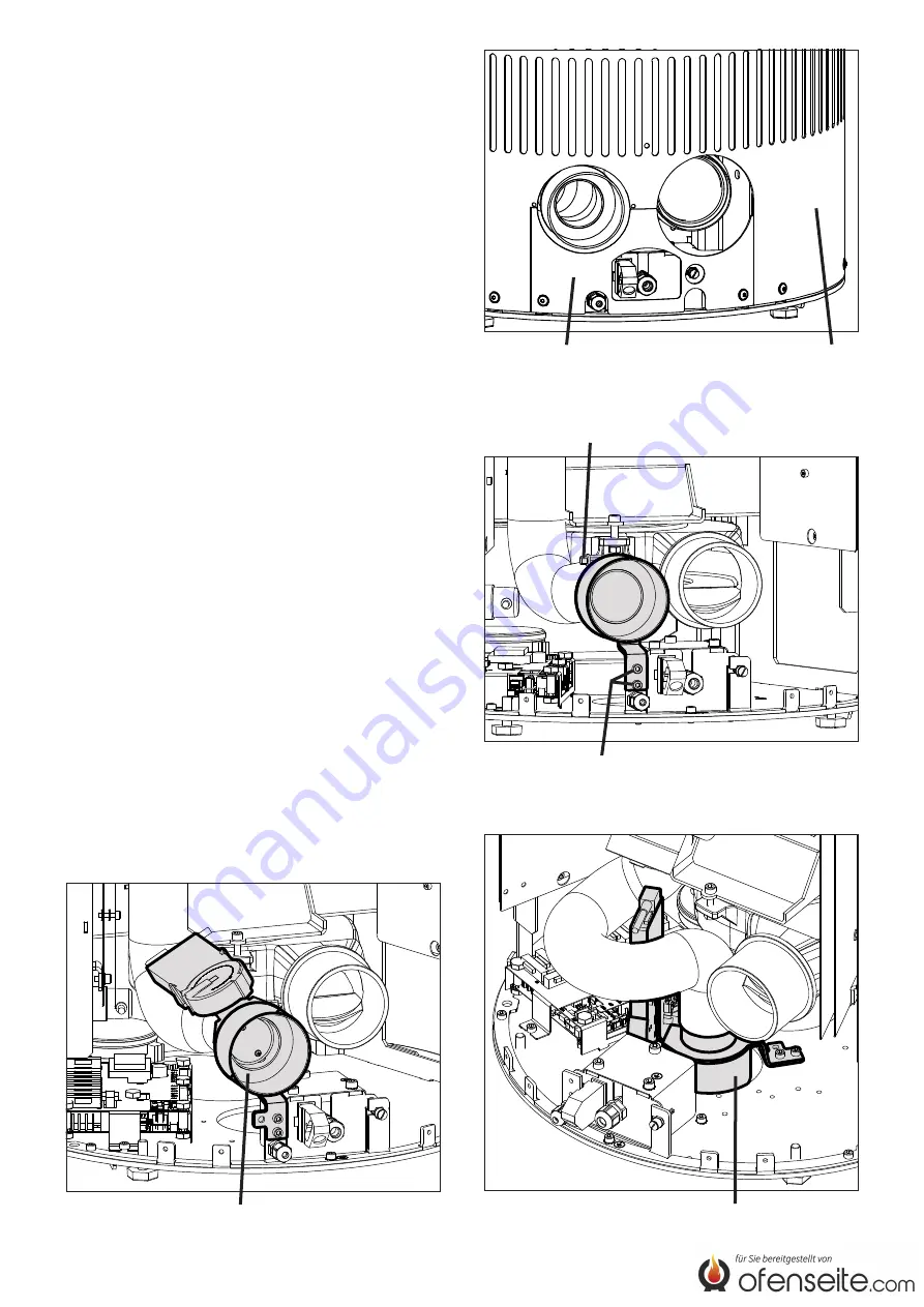
Fig.2

        Panel                                    Lower rear wall

                   Hose clamp

Fig.3

          Screws combustion air duct

Fig.5

  Combustion air damper screwed on 

at the bottom

Installation sequence

If you want to install other accessories in addition to 

the combustion air damper, e.g. a GSM module, you 

always need to install the combustion air damper first 

for reasons of accessibility. For the same reason, you 

can only mount the side panels after you are finished 

installing the combustion air damper.


Dismount the lower rear wall and panel (Fig.2).


Release the hose clamp on the combustion air line 

and remove the combustion air duct (Fig.3).


Wire the plugs as follows before installing the com-

bustion air damper:
a) Connect plug „19“ onto position „S19“ of the main 

circuit board (see connection diagram in the lower 

rear wall / instruction manual of the pellet stove).

b) Connect plug „S5“ onto position „S5“ of the main 

circuit board.

c) Connect plug „L-Dauer“ (“L continuous“) onto plug 

„L-Dauer“ (“L continuous“) of the appliance‘s wir-

ing harness.


Insert the duct of the combustion air damper into the 

combustion air line and re-tighten the hose clamp.


Screw the combustion air damper on at the rear 

(Fig.4) or at the bottom (Fig.5) of the appliance.


Route the cables in such a manner that no hot sur-

faces are touched.


After installing the combustion air damper, avoid 

damage to the cables by making sure that they do 

not rest against the rotating assembly of the motor.


Activate the combustion air damper and check it for 

faultless function (see the following chapters).


Remount the panel and lower rear wall.


If the combustion air damper was screwed on at 

the bottom, the hole in the lower rear wall for the 

combustion air connection at the back needs to be 

sealed with a cover and screws (are included with 

the pellet stove).

Fig.4

  Combustion air damper screwed on 

at the rear

Summary of Contents for 43/1481.9240

Page 1: ...Verbrennungsluftklappe 43 1481 9240 Combustion air damper Clapet d air de combustion Anleitung Seite 2 5 Instruction Page 6 9 Instructions Page 10 13 D GB F...

Page 2: ...llen anderen Betriebszust nden Bereit Z nden Start ist sie ge ffnet Achtung Zum Erreichen der Endposition Zu ben tigt der Stellmotor ca 2 Minuten d h wenn die Anzeige Aus am Display erscheint darf das...

Page 3: ...ckwand bzw in der Ger teanleitung b Stecker S5 auf Position S5 der Hauptplatine aufstecken c Stecker L Dauer auf Stecker L Dauer des Ger te Kabelbaums aufstecken Stutzen der Verbrennungsluftklappe in...

Page 4: ...l St rmeldungen Betriebsdaten Serviceebene ein n v 1 00 35 L6 2000h 0h oder Serviceebene Weiter eingeben Kennwort 0000 oder Das Kennwort f r die Serviceebene lautet 2012 Serviceebene Info Eing nge Par...

Page 5: ...ion gepr ft werden Dazu die Verbrennungsluftklappe im Men Relaistest ein und ausschalten Mit oder und mit ENTER in das Men Relaistest wechseln Relaistest Schnecke Saugzug Z ndung Rost Pumpe Zuluftklap...

Page 6: ...open in all other operation modes standby ignition start Important It takes the servo motor approx 2 minutes to reach the end position Closed i e when the display reads off you must wait for at least...

Page 7: ...pellet stove b Connect plug S5 onto position S5 of the main circuit board c Connect plug L Dauer L continuous onto plug L Dauer L continuous of the appliance s wir ing harness Insert the duct of the c...

Page 8: ...urs Ver ext req GSM mod error messages operating data service level on n c 1 00 35 L6 2000h 0h or Service level next code enter 0000 or The password for the service level is 2012 service level input d...

Page 9: ...do this switch the combustion air damper on and off in the relay test menu Go to the relay test menu using or and ENTER relay test auger exhaust ignition grate pump supply air convection off off off...

Page 10: ...de service standby allumer d part il est ouvert Attention Il faut environ 2 minutes au moteur de com mande pour atteindre la position finale fer m c est dire que lorsque l annonce off s affiche l cra...

Page 11: ...u dans le ma nuel d instruction de l appareil b Enficher le connecteur S5 en position S5 de la carte syst me c Enficher le connecteur L Dauer L Dur e sur le connecteur L Dauer L Dur e du fais ceau de...

Page 12: ...therm ext mod GSM info d erreurs information menu SAV on n i 1 00 35 L6 2000h 0h ou menu SAV suiv code entrer 0000 ou Le mot de passe pour le menu SAV est 2012 menu SAV info param tres test sortie ac...

Page 13: ...ur ceci allumer et teindre le clapet d air de combustion dans le menu test sor tie Passer au menu test sortie avec ou et avec ENTER test sortie vis sans fin extracteur allumage grille pompe air combus...

Page 14: ...14...

Page 15: ...15...

Page 16: ...1 78 4643 1486 07 2015 Olsberg GmbH H ttenstra e 38 59939 Olsberg T 49 2962 805 0 F 49 2962 805 180 info olsberg com olsberg com...

Reviews: