background image

12

Installing the stove

The floor on which the stove is installed must be even and 

horizontal. The stove may only be installed on an adequate 

load-bearing floor. The stove can be stood on a  metal floor 

sheet or glass sheet to protect the flooring.

If the flooring or carpet is inflammable, a stable and non-

combustible spark protection plate must be used. This 

must extend 50 cm to the front and 30 cm to each side 

beyond the edge of the combustion chamber opening. 

Under the stove no spark protection plate is required.

Assembly sequence


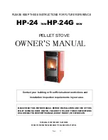
The Ø150mm stovepipe connection can be installed at 

the top or rear. The stove is supplied ready for connec-

tion from above. If you wish to connect it at the rear, the 

following steps must be carried out to make the neces-

sary modifications:
-  Break out the cover “A” in the back panel.
-  Replace the back cover “B” with the connector cover. 


Decide where the stove is to be installed. There must be 

no objects made of combustible materials within a dis-

tance of 75 cm,


 of the stove’s radiation area, measured 

from the combustion chamber’s inspection glass, nor 

may any be placed within this area subsequently.
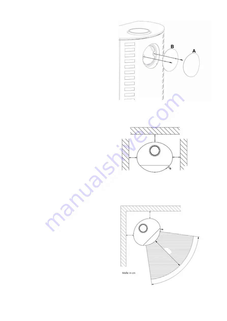
Depending on the installation position of the stove in 

front of walls that need to be protected (flammable or 

load-bearing), the following distances from walls need 

to be observed in accordance with the position of the 

combustion chamber door to the wall / side panel or 

the back panel (see schematic diagram).

When not dealing with walls that need to be protect-

ed, you merely need to observe a minimum distance of 

approx. 5 cm to allow for proper heat dissipation.


Install the pipe lining (provided on site) in the chimney. 

The connection height can be individually specified for 

a top stovepipe connection, however should not exceed 

1.5 m from the connector sleeve. For the rear stovepipe 

connection heights please refer the “Technical Data“ 

chapter. No combustible material is permitted within a 

radius of 20 cm around the stove pipe.


Connect the stovepipe at both connection points with 

stove putty so that the stove pipe is permanently sealed.


Push the stove onto its planned position and orient it so 

that the stovepipe fits into the pipe lining.

The stovepipe connections must be tight. The stove-

pipe must not protrude into the chimney.
Bear in mind that on partition walls in accordance with 

test specification EN 13240 the temperature of 85°C 

can be reached, and with light wallpaper or similar 

combustible construction materials this can result in 

colour changes.

20

20

20

Dimensions in cm

Stove installed straight in corner

20

20

75

80°

Stove installed diagonally in corner

Summary of Contents for Libra

Page 1: ...Kaminofen Libra 28 915 DIN EN 13240 15a BV G EN D F Anleitung Seite 2 9 Instruction Page 10 16 Instructions Page 17 23...

Page 2: ...r die richtige Bedienung informieren k nnen Transportsch den sind umgehend innerhalb von 2Ta gen an Ihren Lieferanten zu melden Technische Daten Nennw rmeleistung 5 0 kW Raumw rmeleistung 5 4 kW Ansch...

Page 3: ...dichte Leitung oder ber ein LAS System zugef hrt werden Sprechen Sie deshalb mit Ihrem Bezirksschornsteinfegermeister Aus Energiespargr nden EnEV sollte bei Nichtbetrieb des Kaminofens die Verbrennun...

Page 4: ...inofen vor zu sch tzen den W nden brennbar oder tragend montiert wird sind entsprechend der Position der Feuerraumt r zur Aufstell bzw Seiten oder R ckwand folgende Wandabst nde einzuhalten siehe Prin...

Page 5: ...pier und Pappe au er zum Anz nden Stroh Beachten Sie vor dem ersten Heizen Alle Zubeh rteile aus dem Aschekasten und Feuerraum entnehmen Der auftretende Geruch durch das Verdampfen der Schutzlackierun...

Page 6: ...Abbrand mindestens auf I zu stellen Dies gilt auch bei Schwachlastbetrieb Bei Nichtbetrieb den Bedienhebel auf 0 stellen um ein Ausk hlen des Aufstellraumes zu verhindern Feuerrost Bedienhebel f r de...

Page 7: ...mmen Was tun Verbrennungsluftschieber ganz ffnen Nur kleine Menge Brennstoff auflegen Asche h ufig sch ren Verkleidung Die Verkleidungen d rfen nicht berheizt werden da sonst Risse auftreten k nnen Mi...

Page 8: ...einzutragen Typnummer 28 __________ Fabrikationsnummer _________________________ Was ist wenn der Kaminofen nicht richtig zieht Ist der Schornstein oder das Ofenrohr undicht Ist der Schornstein nicht...

Page 9: ...tellt Farbun terschiede bei Glasuren sowohl in Helligkeit als auch Farbt nung k nnen von Keramikbrand zu Keramik brand in Nuancen auftreten Diese Unterschiede k nnen deutlich bei Lieferung von einzeln...

Page 10: ...ty space heating without having to do without the cosy atmosphere of an open fire Proper installation and correct handling and care are in dispensable for problem free operation and a long ser vice li...

Page 11: ...gh a supply duct in the chimney Thus speak with your district chimney sweep master Due to energy saving reasons the combustion air inlet should be able to be blocked if the stove is not being op erate...

Page 12: ...that need to be protected flammable or load bearing the following distances from walls need to be observed in accordance with the position of the combustion chamber door to the wall side panel or the...

Page 13: ...ollowing fuels in stoves Moist wood or wood treated with wood preservatives Sawdust chippings grinding dust Bark and chipboard waste Slack coal Other wastes Paper and cardboard except for igniting Str...

Page 14: ...e secondary air also contributes to the cleanliness of the glass pane the operating lever should be set on I minimum This also applies in the event of low load operation When not operating the lever s...

Page 15: ...gh above 16 C the delivery pres sure can be disrupted What to do Open the combustion air slide valve complete Only put on a small quantity of fuel Frequently stoke the ash Cladding The cladding may no...

Page 16: ...hand Type number 28 __________ Fabrication number __________________________ What to do if the stove doesn t draw properly Is the chimney or the stovepipe not tight Has the chimney been incorrectly de...

Page 17: ...e int rieur de qualit sans devoir renon cer l atmosph re douillet d un feu de chemin e L installation en bonne et due forme ainsi que le manie ment et l entretien correct du po le sont indispensables...

Page 18: ...tion est plus long que 3 m il faut fournir le calcul jus tificatif pour l alimentation en air de combustion Dans le cas de tr s basses temp ratures ext rieures de la conden sation peut se former sur l...

Page 19: ...a porte du foyer de respecter les carts suivants avec le mur d installation le panneau la t ral ou arri re voir sch ma de principe Si le po le n est pas mont proximit de murs pro t ger il convient de...

Page 20: ...mbustibles suivants dans les po les chemin e Bois humide resp trait avec des produits de pr servation du bois Sciure de bois copeaux poussi re de meulage D chets d corce et d agglom r s Menus de houil...

Page 21: ...res il faut toujours placer le levier de commande au minimum sur I durant la combustion Ceci est aussi valable en cas d exploitation charge r duite Lorsque l appareil est teint placer le levier de com...

Page 22: ...gistre d air de combustion tout fait N alimenter qu avec de petites quantit s de combustible Attiser souvent la cendre Habillage Il ne faut pas surchauffer l habillage car on pourrait vo quer des craq...

Page 23: ...tion Num ro de s rie 28 __________ Num ro de fabrication ________________________ Que faut il faire si le po le ne tire pas bien La chemin e ou le tuyau de chemin e ne sont ils pas tanches La chemin e...

Page 24: ...78 4628 9151 R 01 08 2019 Olsberg GmbH H ttenstra e 38 59939 Olsberg T 49 2962 805 0 F 49 2962 805 180 info olsberg com olsberg com...

Reviews: