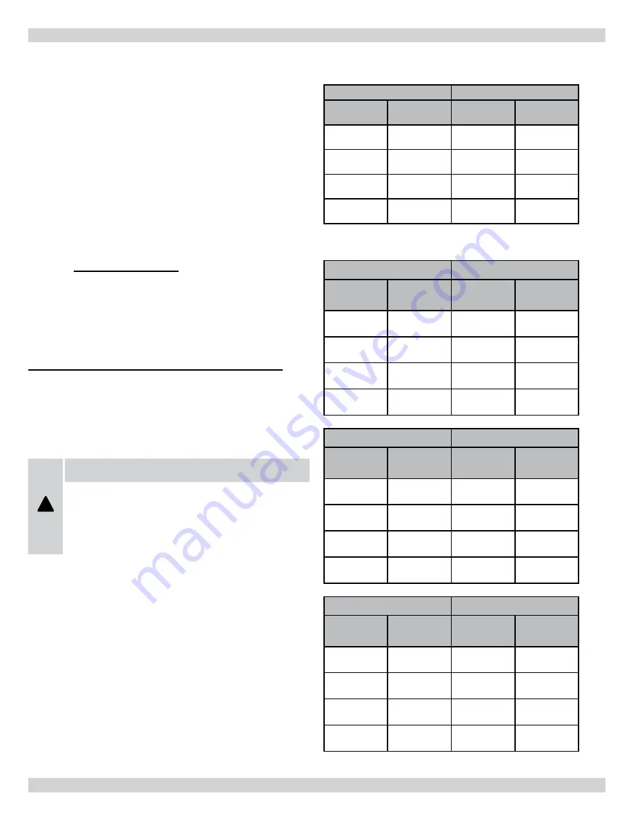
TABLE 11A - HEATING SPEEDS
ALL MODELS
ESP 0.1” to 1.0” w.c.
HEAT
Jumper
ADJUST
Jumper
Low-Fire
▲
T
Range 25-55 °F
High-Fire
▲
T
Range 35-65 °F
A
NORM
40 °F
50 °F
B
NORM
35 °F
45 °F
C
NORM
45 °F
55 °F
D
NORM
50 °F
60 °F
Note: Moving the ADJUST jumper from the NORM position to the
(+) or (-) position will increase or lower the temperature rise by 15%
TABLE 11B - HEATING CFM
95V060-3
ESP 0.1” to 1.0” w.c.
HEAT
Jumper
ADJUST
Jumper
Low-Fire
CFM
High-Fire
CFM
A
NORM
700
1050
B
NORM
850
1105
C
NORM
575
880
D
NORM
525
819
TABLE 11C- HEATING CFM
95V080-4
ESP 0.1” to 1.0” w.c.
HEAT
Jumper
ADJUST
Jumper
Low-Fire
CFM
High-Fire
CFM
A
NORM
1000
1350
B
NORM
1150
1495
C
NORM
900
1206
D
NORM
800
1104
TABLE 11D HEATING CFM
95V120-5
ESP 0.1” to 1.0” w.c.
HEAT
Jumper
ADJUST
Jumper
Low-Fire
CFM
High-Fire
CFM
A
NORM
1650
2200*
B
NORM
1900
2200*
C
NORM
1500
2070
D
NORM
1325
1815
* Motor CFM maxium
Calculating Air Flow
Th
ere are circumstances where it may be desirable to know the air
fl ow delivery through the duct
system, such as when estimating the amount of air fl ow available for
air conditioning. Th
is can be done by direct measurement with elec-
tronic or sloped manometers and velometers, or by counting the
number of times the amber CFM LED on the control board fl ashes.
Each fl ash signifi es 100 CFM; count the fl ashes and multiply by 100
to determine the actual CFM delivered (for example: 10 fl ashes x 100
= 1000 CFM). Or use the formula in the next column.
CFM =
Output
1.085 x
∆
T
where:
• CFM is air
fl
ow in cubic feet per minute;
•
∆
T is the temperature rise; and
• O
utput is the furnace output capacity from
the rating plate
.
NOTE:
Output will vary directly with the input. If the
actual input is below the stated input, the output will
be reduced in the same ratio (93%).
Adjusting Blower Speeds
!
WARNING
DISCONNECT THE ELECTRICAL SUPPLY TO THE
FURNACE BEFORE ATTEMPTING TO CHANGE THE
BLOWER SPEED. FAILURE TO DO SO COULD RESULT
IN ELECTRICAL SHOCK RESULTING IN PERSONAL
INJURY OR LOSS OF LIFE.
Th
is unit is factory set to run at the middle of the heating tempera-
ture rise range as listed on the rating plate. Th
e cooling speed is set
to the maximum airfl ow designated in the model number.
Th
ree sets of 4 position movable jumpers are provided for Heat,
Cool, and Adjust taps for a variable speed motor. Th
ese tap jumpers
apply signals to the ECM motor without other interaction with the
control board.
23 - AIR FLOW
45


