Dehumidifi cation:
For situations where humidity control is a problem, a dehumidifi ca-
tion feature has been built into the variable speed motor. At the start
of each cooling cycle, the variable speed motor will run at 82% of
the rated airfl ow for 7.5 minutes. Aft er 7.5 minutes has elapsed, the
motor will increase to 100% of the rated airfl ow. If this feature is not
desired, clip the jumper wire between Y and O on the integrated
furnace control board. With Y and O not jumpered, the variable
speed will reach 100% of the rated airfl ow within 10 seconds of a call
for cooling.
Additional dehumidifi cation can be achieved by connecting a hu-
midistat to the DEHUM and R terminals on the integrated furnace
control board. In this setup, the variable speed motor will operate at
a 10% reduction in the normal cooling airfl ow rate when there is a
call for dehumidifi cation.
Both dehumidifi cation methods described above can be utilized on
the same furnace.
Setting Blower “On” And “Off ” Timings
Blower on/off delays are handled by ECM
motor programming. Th
e control de-energizes the ECM heat signal
when the gas valve de-energizes. Features of this ECM variable speed
motor are that it will deliver a constant airfl ow within a wide range
of external static pressures, and also includes:
Soft Start:
This ECM variable speed motor will slowly ramp
up to the required operating speed. This feature in the heating
cycle allows the heat exchanger to reach operating tempera-
ture before the set heat speed, which minimizes noise and
increases comfort.
Soft Stop:
At the end of the heating or cooling
cycle, the ECM variable speed motor will slowly ramp down.
This feature allows for increased
energy ef
fi
ciency, and reduced noise levels.
Continuous Fan Operation
When the thermostat continuous fan (G) switch is on without a call
for heat or cooling, the indoor fan is immediately energized up to
50% of the cooling speed. Th
e fan remains energized as long as the
call for fan remains without a call for heat or cooling. Th is feature
allows continuous circulation of air between calls for heating or
cooling.
If a call for heat (W) occurs during continuous fan, the blower will
de-energize.
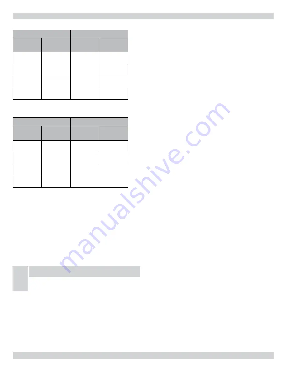
TABLE 11E HEATING CFM
95V080-3
ESP 0.1” to 1.0” w.c.
HEAT
Jumper
ADJUST
Jumper
Low-Fire
CFM
High-Fire
CFM
A
NORM
1050
1376
B
NORM
1250
1400*
C
NORM
900
1242
D
NORM
780
1108
* Motor CFM maximum\
TABLE 11E HEATING CFM
95V100-5
ESP 0.1” to 1.0” w.c.
HEAT
Jumper
ADJUST
Jumper
Low-Fire
CFM
High-Fire
CFM
A
NORM
1200
1620
B
NORM
1400
1820
C
NORM
1100
1474
D
NORM
950
1349
Note: Moving the ADJUST jumper from the NORM position to the
(+) or (-) position will increase or lower the temperature rise
by 15%
If the blower speeds require adjustment, follow these steps:
1.
Remove the blower compartment door.
2.
Locate the 4 position movable HEAT jumper to adjust heat
speed.
3.
Remove the jumper from position A
and place it on the corresponding letter B, C,
or D as required. Refer to
TABLE 11A-11E HEATING-
SPEEDS.
NOTICE
NOTE: Temperature rise should always be re-checked
whenever blower speed is changed.
4.
To adjust the cooling airfl ow, remove the COOL jumper from
position A and place it on the corrosponding letter B, C, or D.
Refer to
TABLE 10 AIR FLOW
.
Moving the ADJUST jumper from the NORM to the (+) or (-) posi-
tion will cause the airfl ow to be increased or lowered by 15%.
Th
e TEST position on the ADJUST tap is not used.
23 - AIR FLOW
46


