NOTICE
IMPORTANT: If an air conditioning evaporator coil drain
is to share the furnace drain line, it should be connected
with a tee fi tting downstream from the trap. Do not con-
nect the evaporator coil condensate drain upstream of the
furnace drain trap assembly.
Condensate Neutralizers
Some local codes may require the use of a condensate neutralizer. If
the furnace condensate is to be routed to a septic system, it may be
advisable to use a condensate neutralizer.
Condensate neutralizers such as the Ward Industries 90+ Neutralizer
are available through heating supply wholesalers.
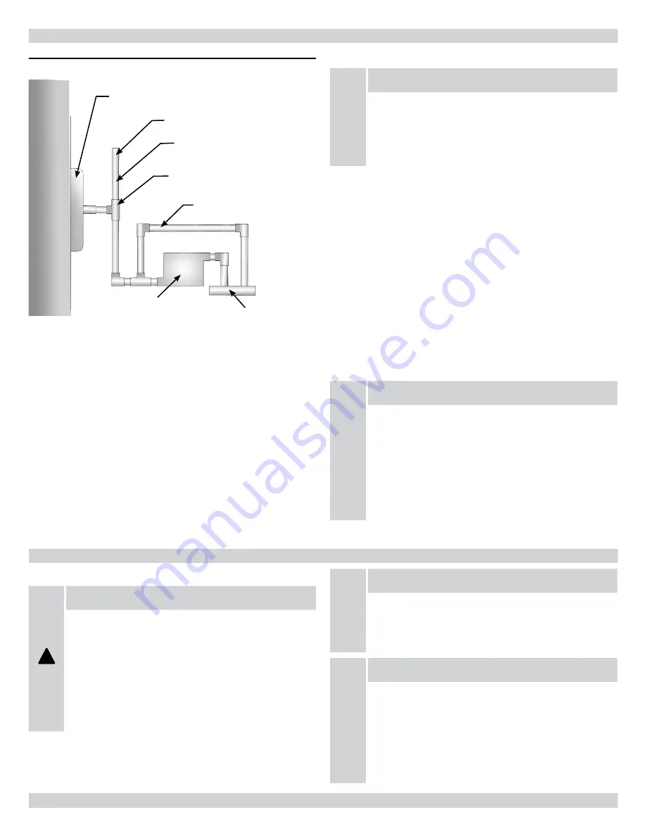
When condensate neutralizers are used, it is advisable to install it
with an overfl ow bypass tube. (
Figure 27)
NOTICE
IMPORTANT: Th
e condensate drain trap assembly should
be full of water before starting the furnace. To fi ll the con-
densate drain trap assembly, temporarily remove the vent
drain hose from the induced blower assembly elbow/drain
fi tting, and pour approximately one cup of water down the
hose. Water will begin running out the condensate drain
trap outlet when it is full. Refasten the vent drain hose to
the induced blower assembly elbow/drain fi tting.
Figure 27 - Condensate Bypass
G95V
UNIT
OLSEN DRAIN TRAP
ASM
VENT
1/2" PIPE
& FITTINGS
NEUTRALIZER BYPASS
CONDENSATE NEUTRALIZER
(IF REQUIRED)
DRAIN
VENT HEIGHT MUST BE 1"
ABOVE RECOVERY COIL
Th
e condensate drainage confi guration requires a vent. It takes less
than a one inch rise anywhere along the horizontal route of the drain
tube to create a vapor lock, which will prevent condensate from
draining away freely, and result in erratic furnace operation.
A typical confi guration would be to cement the side branch of a ½”
PVC tee to the drain trap assembly outlet, with the end branches
oriented vertically. (
Figure 27
)
A 1” piece of ½” PVC pipe cemented to the upper end branch will
serve as a vent, which will prevent the creation of a vapor lock,
and serve as an overfl ow in the event that the drain line becomes
blocked. A similarly sized piece of pipe cemented to the lower end
branch will permit connection to the condensate outlet with ⅝” ID
/ ⅞” OD fl exible tubing, or the condensate may be piped entirely in
PVC to the fl oor drain/sump/condensate pump.
16 - CONDENSATE DRAINS
Gas Supply
!
WARNING
THIS FURNACE IS FACTORY EQUIPPED TO BURN
NATURAL GAS ONLY.
CONVERSION TO LP GAS REQUIRES SPECIAL NATU-
RAL GAS TO LP CONVERSION KIT.
FAILURE TO USE THE PROPER CONVERSION KIT
CAN CAUSE FIRE, EXPLOSION, CARBON MONOX-
IDE POISONING, PROPERTY DAMAGE, PERSONAL
INJURY OR LOSS OF LIFE.
NOTICE
IMPORTANT: Conversion of this furnace requires
specialized equipment. Conversion must be completed
by a trained and qualifi ed installer, service agency or gas
supplier.
NOTICE
IMPORTANT: Connect this furnace only to gas supplied
by a commercial utility or supplier. Private gas wells do not
generally provide gas with consistent, uniform and pre-
dictable heating values and densities. Many non-commer-
cial wells contain impurities such as sulphur, which may
damage the furnace. Th
is furnace cannot operate properly
or safely using fuels outside normal commercial standards.
17 - GAS SUPPLY AND PIPING
34

