Single Stage Thermostat
Th
e automatic heat staging option allows a single stage thermostat
to be used with a two stage furnace. Th
e control provides a movable
jumper (P5) to select between 5 minute and *10 minute automatic
staging. Automatic staging time begins when the blower is energized
aft er the heat blower delay period. If the jumper is in the 5 min-
ute position, the control will automatically start high heat aft er 5
minutes of continuous low heat operation. If the jumper is in the
*10 minute position, the control will automatically start high heat
aft er 10 minutes of continuous low heat operation. Once high heat
is started from automatic staging, the demand for high heat remains
until the heat call is satisfi ed.
* Factory Setting
Two Stage Thermostat
When connecting a two stage thermostat, the jumper (P5) must be
in the “NONE” position. Th
e control runs high heat from the ther-
mostat W2 demand.
Thermostat Location
Th
e thermostat should be located approximately 5 feet above the fl oor,
on an inside wall where there is good natural air circulation, and where
the thermostat will be exposed to average room temperatures. Avoid
locations where the thermostat will be exposed to cold draft s, heat from
nearby lamps or appliances, exposure to sunlight, heat from inside wall
stacks, etc.
Thermostat Heat Anticipator Setting: 0.1 AMP (Honeywell)
Th
e low voltage terminals are located in the control box mounted to
the blower assembly. Th
e furnace is air conditioning ready. Insert the
thermostat and air conditioner contactor low voltage wiring through
a knockout provided in the side panel above the supply voltage
knockout using a fi eld supplied bushing. Route the control wiring to
the control panel to connect to the 24 volt terminal screws.
Thermostat
Th
e room thermostat must be compatible with the integrated control
in the furnace. Electro-mechanical thermostats should be rated 30 V
/ 1.5 amps.
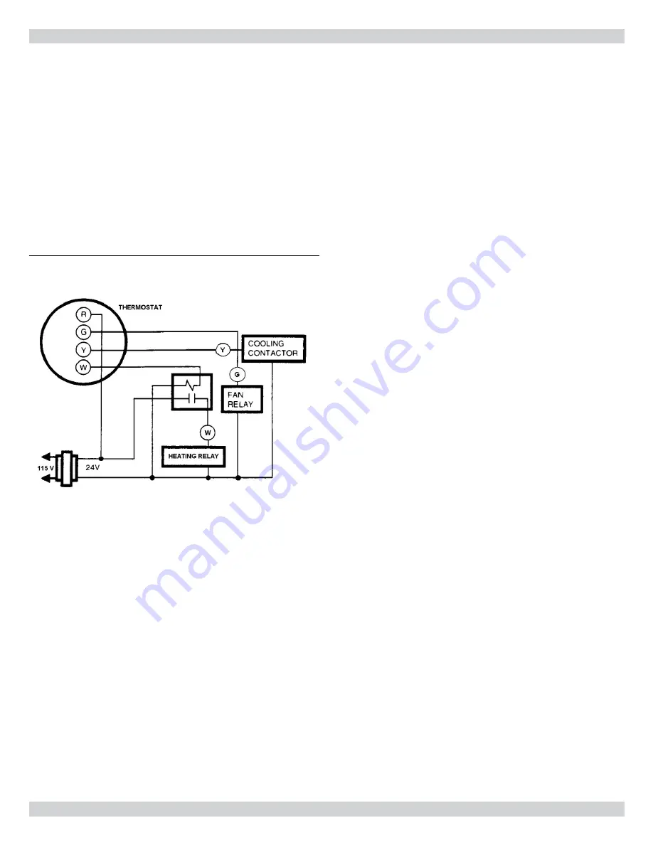
Figure 36- Isolation Relay
Most electronic or microprocessor based thermostats except those
with “current robbing” circuits should work satisfactorily. Consult
the instructions of the thermostat manufacturer for technical and
installation details.
Most compatibility problems can be overcome by
the use of an isolation relay. Th
e isolation relay should be SPST with
a 24 volt coil. Th
e switch ratings should be a minimum of 0.5 amps.
(
Figure 36
)
Th
e thermostat and control wiring should be a minimum of 18 AWG
copper. Excessive lengths of wire may result in enough voltage drop
to impair the proper functioning of the furnace. For thermostat
wires in excess of 25 feet, use 16 AWG; 50 feet, use 14 AWG.
20 - LOW VOLTAGE WIRING
41


