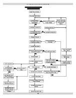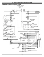
Sequence Of Operation
1.
Room temperature drops causing the room thermostat to call
for fi rst stage heat by connecting “W1” to “R”. Th
e control veri-
fi es the limit switch is closed and both low and high pressure
switches are open. Th
e control energizes the induced draft mo-
tor on high speed and waits for the low pressure switch to close.
Th
e inducer remains on high speed and begins a 15 second pre-
purge period. Th
e high pressure switch is ignored. If the low
pressure switch does not close within 60 seconds, the control
will fl ash “2” on the red Status LED, and de-energize the
inducer for 60 minutes.
2.
When the 15 second pre-purge time has elapsed, the control en-
ergizes the HSI output for a 5 second warm-up period (10 sec-
onds on retries). Th
e control energizes the low main gas valve.
4 seconds aft er the gas is energized, the control de-energizes the
HSI output and leaves the gas energized another 1 second for
fl ame proving. If fl ame is present at the end of trial for ignition
time, the control leaves the gas valve energized, inducer on high
speed, and begins heat blower on delay. Th
e control always
ignites on high inducer/low gas and ignores second stage call
for heat until low heat is established for
15 seconds.
3.
Blower on delay time begins when the gas valve is energized.
Th
e control provides the ECM (Electronically Commutated
Motor) low heat speed signal when fl ame is proven, and starts
a 30 second soft start (slowly ramp up) blower delay before full
capacity blower level.
4.
When there is a demand for 2nd stage heat from thermostat W2
or automatic staging, the control changes the inducer from low
to high speed. When high pressure switch closes, the control
changes indoor blower speed from Low heat to High heat and
energizes high gas output. If the High pressure switch is open
the Green LED will fl ash. If the High pressure switch is closed
the Green LED will be on. High gas valve drops out while High
pressure switch is open because it is directly in series with the
High pressure switch.
5.
When the thermostat W2 call ends and W1 remains (two stage
thermostat), the control de-energizes the high gas output and
immediately changes inducer speed from high to low. With the
thermostat heating contacts open (single stage thermostat), the
fl ames extinguish immediately and the inducer blower stops
aft er a 5 second post purge time.
6.
Blower off delay is handled by the ECM
(Electronically Commutated Motor). Th
e control de-energizes
the ECM heat signal when the gas valve de-energizes, and starts
a programmed soft stop (slowly ramp down) delay period.
In The Event Of Flame Failure:
If fl ame is lost, the control de-energizes the gas valve within 2 sec-
onds, switches the induced draft motor to high speed (if not already
on high), and begins timing the inter-purge delay. Th
e indoor blower
motor will be energized and/or remain energized on heat speed for
the programmed delay off time. When the inter-purge delay is over,
the control will re-cycle up to 5 fl ame losses (4 re-cycles) within a
single call for heat before going into lockout. Th e control fl ashes “8”
on the red LED if lockout is due to too many fl ame losses.
Checking Furnace Input
Th
e natural gas supply pressure should be a maximum of 7” w.c. and
minimum of 5” w.c. Th
e burner manifold pressure is factory set to
3.5” w.c. High Fire, 1.5” w.c. Low Fire. Th
e input rating of the fur-
nace is based on 1000 BTU/cu. ft . gas with a specifi c gravity of 0.6.
Since heating values for the gas vary geographically, the actual fur-
nace input and output will vary accordingly. For example, natural gas
with a 1000 BTU/cu. ft . heating value will reduce the input to 93%
of the rated input. Natural gas with a 1100 BTU/cu. ft . heating value
will increase the input to approximately 103% of the rated input. Th is
is not usually a problem; however, adjustments to compensate for
this can be made by minor adjustments to the burner manifold pres-
sure or by changing the burner orifi ce size.
Any adjustments to the burner manifold pressure should be carried
out with the use of a manometer or calibrated magnehelic gauge. Do
not adjust the gas valve pressure regulator more than ±0.3” w.c.
NOTICE
IMPORTANT: Never adjust the input of the furnace to
exceed the input shown on the rating plate.
which should be followed to ensure proper installation and
operation.
In the previous example where the heating value of the gas is 1100
BTU/cu. ft ., the burner manifold pressure can be reduced 3% to 3.4”
w.c., which is within the ±0.3” w.c. specifi cation to bring the input
into compliance. Refer also to “Setting the Gas Manifold Pressure”
and “High Altitude in the Gas Supply & Piping” section of this man-
ual. Contact the fuel supplier for specifi c gas heating content values.
Input =
Heating Value of Gas x 3600
Time in Sec. for 1 cu. ft.
where:
•
input is expressed in BTU/Hr
•
heating value of the gas is expressed in BTU/ft
3
• and time is the number of seconds required for
the test dial to indicate 1 cubic foot.
If using a gas meter with SI (metric) units:
•
1 cubic foot = 0.0283 cubic meters
•
1 cubic meter = 35.315 cubic feet
•
0.01 cubic meter = 0.3531 cubic feet
•
0.5 cubic meter = 1.766 cubic feet
22 - STARTUP PROCEDURES
43


