background image

34

HEATING & COOLING

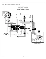
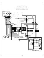
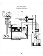
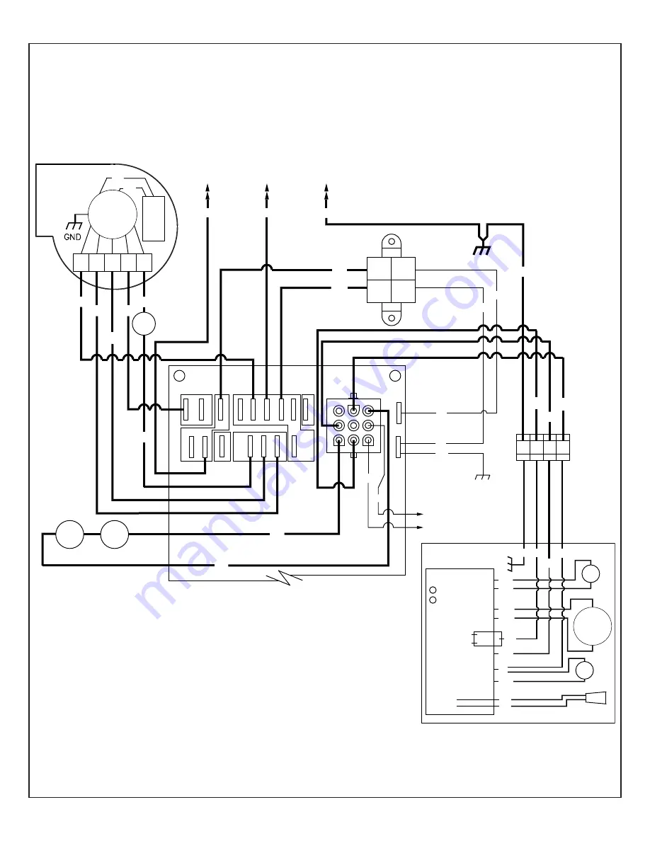
BECKETT WIRING DIAGRAM 

VI

WH

L2 (WHITE)

IGNITER (BLUE/WHITE)

(YELLOW)

FLAME SENSOR

sonde a flame

VI

BL

OR

WH

BK

YL

YL

BECKETT AF BURNER/brûleur

moteur

MOTOR

V

I

BECKETT OIL

PRIMARY

CONTROL

L2 (WHITE)

L2 (WHITE)

VALVE (VIOLET)

MOTOR (ORANGE)

LIMIT (RED)

L1 (BLACK)

L2 (WHITE)

CAD CELL

WH

WH

WH

TR

TW

GR BK

GND

BR

BR

CAP

WH

BK

GND

YL

BL

MOTOR

1 2

4

3

5

3

U

N

U

SE

D

1 2

EAC

CONT

COOL

HEAT

6 7

HUM

X

C

F

TRANSFORMER/

MHI

3

1 2

4

H

C

L

ML

N

WH

BK

BL

YL

YL

WH

BK

BK

1

2

4 3

VI

WH

RD

RD

BL

120V 24V

24V

COM

GR

TW (T)

TR (T)

BVS

L

BLOWER

ventilateur

principale

INDOOR

moteur

MOTOR

transformateur

1158-1/1168-1 CONTROL

L1

YL

BL

COM

R

C

YL

GR

GND

GR

N

GND

RD

Summary of Contents for HTL-100

Page 1: ...ALLATIONS MUST MEET ALL LOCAL AND FEDERAL CODES THAT MAY DIFFER FROM THIS MANUAL Please read the manual in its entirety before beginning installation This manual must be kept with the boiler for futur...

Page 2: ...LLATION OF BURNER 17 5 2 SET BURNER FOR EFFICIENT OPERATION 18 5 3 HTL TECHNICAL INFORMATION 20 6 0 FURNACE OPERATION AND SETTINGS 23 6 1 BOILER SETTING 23 6 2 FAN TIMER CONTROL BOARD 1158 120 23 6 3...

Page 3: ...r any oil containing gasoline CAUTION DO NOT TAMPER WITH THE FURNACE OR CONTROLS CALL A QUALIFIED BURNER TECHNICIAN If lock out condition occurs do not attempt to reset control Contact qualified insta...

Page 4: ...240 mm AIR BLOWER DATA Maximum external static pressure 0 50 WC Maximum cooling unit capacity HTL 100 up to 3 0 tons HTL 200 up to 5 0 tons Maximum air temperature rise 85 F MOTOR BLOWER HTL 100 1 2...

Page 5: ...equipment especially in areas where colder weather has had historic precedent for the type of fuel selected ELECTRICAL 120 Volts 1PH 60 Hz 15 amps circuit protection USA circuit protection 20 amps AIR...

Page 6: ...h 24 1 2 622 mm Height 54 1372 mm Width 21 1 2 546 mm DIMENSIONS HTL 200 Depth 29 1 2 750 mm Height 60 1524 mm Width 24 1 2 622 mm 24 7 8 54 21 5 16 31 3 8 10 5 8 47 7 16 24 1 2 24 1 2 HTL 100 DIMENSI...

Page 7: ...7 25 5 8 60 26 5 16 31 1 8 10 5 8 54 11 16 24 1 2 29 1 2 HTL 200 DIMENSIONS Dimensions are in inches...

Page 8: ...stem packing gland nut on any valves installed in the suction line Also be sure the oil filter is tight as filter gaskets often shrink Check for kinks in the oil lines as well as for possible air pock...

Page 9: ...flue pipe as short as possible with min 1 4 per foot upward slope Vent flue pipes MUST NOT pass through a ceiling Maximum flue gas temperature is 575 F PRESENCE OF CONDENSATION IN THE CHIMNEY OR FLUE...

Page 10: ...oor or stairway to furnace room so furnace can be shut off remotely COMBUSTION VENTILATION AIR Oil fired appliances shall be connected to vents having sufficient draft at all times to provide safe and...

Page 11: ...air and additional ventilation from outdoor The opening shall have a total free flow area of not less than 4 4 cm2 kW 1 in2 5000 BTU h of the total input rating for the appliance s located in a large...

Page 12: ...ning shall have a free flow area of not less than 22 cm2 kW 1 in2 1000 BTU h of the input rating of the appliance s located in the limited space 4 0 ACCESSORIES INSTALLATION BLOCKED VENT SWITCH BVSO F...

Page 13: ...O wiring diagram Wiring Instructions BVSO Caution Disconnect the electrical power when wiring the unit Wire the blocked vent switch in accordance with The National Electrical Code and applicable local...

Page 14: ...cause products of combustion to enter the house Wire as per wiring label and diagram Height of the coil above the unit shall be at least 4 102 mm HUMIDIFIER If a humidifier is installed ensure that no...

Page 15: ...the position that he wants There are 3 possible locations to install the air filter rack which are bottom left side bottom right side and under the furnace Follow the instructions below to install the...

Page 16: ...right side or base panel where you want to install the air filter Step 6 Cut the panel between the 4 knockouts Step 7 Using 8 screws install the air filter rack on the furnace Seal Properly Step 8 Sli...

Page 17: ...t setting HTL 100 162 240 6 3 8 9 1 2 HTL 200 INSERTION IMPORTANT When installing the burner on the furnace MOUNT BURNER make sure that the burner head does not damage the firepot If the burner head t...

Page 18: ...er the AFG designation and the static disk size after the head model information For example the AFG F0 3 3 8 means an AFG chassis burner with a F0 head and a static disk of 3 3 8 PUMP PRESSURE Refer...

Page 19: ...ke test reading a 10 full slow steady pump action is required Lower the CO2 reading noted before by the value of 1 by opening the air gate of the burner CO2 test can be done mechanically activate 18 f...

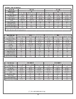
Page 20: ...000 Output BTU h 65 000 76 000 87 000 100 000 110 000 127 000 Nozzle 0 50 70 B 0 60 70 W 0 65 70 W 0 75 70 W 0 85 70 W 1 00 70 B Static Disk 3 5 8 U 3 3 8 U 3 3 8 U 2 3 4 U 2 3 4 U 2 3 4 U Head F0 F0...

Page 21: ...49 600 Output BTU h 62 000 74 000 85 000 98 200 108 500 124 000 Nozzle 0 50 70 B 0 60 70 W 0 65 70 W 0 75 70 W 0 85 70 W 1 00 70 B Static Disk 3 5 8 U 3 3 8 U 3 3 8 U 2 3 4 U 2 3 4 U 2 3 4 U Head F0 F...

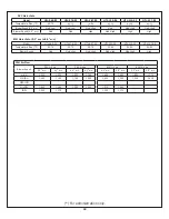
Page 22: ...03 HTL 076 03 HTL 087 03 HTL 100 05 HTL 110 05 HTL 127 05 Temperature Rise F 40 70 40 70 45 75 50 80 50 80 50 80 Blower Speed Med Med High Med High Med High Med High High CFM Air Flow Blower Speed PSC...

Page 23: ...and check that the furnace starts and operates as usual OPERATION If the furnace system fails to operate or operates in an unusual manner call your service technician If the burner fails to operate at...

Page 24: ...n burner motor is de energized at end of call for heat Blower shutdown is delayed to remove any residual heat from heat exchanger Electronic fan timer board works in conjunction with snap disc limit c...

Page 25: ...nals are de energized Cooling contactor is de energized immediately Circulator fan turns off immediately FAN Thermostat begins call for fan G terminal is energized Circulator fan is energized immediat...

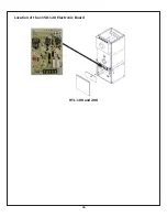
Page 26: ...26 Location of the 1158 120 Electronic Board HTL 100 and 200...

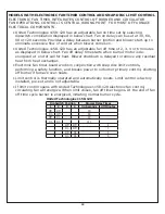
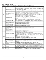
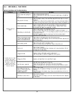
Page 27: ...wiring for short circuits Check for room light leaking into cad cell compartment Repair light leak if necessary Open safety switch Check for open limit or auxiliary limit Check internal wiring connec...

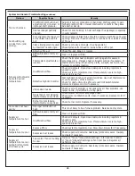
Page 28: ...il line Gently warm oil line Insulate oil line Outdoor piping size may require increased diameter Oil burner sputtering at nozzle Electrodes out of adjustment or defective Check electrode settings Che...

Page 29: ...high speed up blower fan Defective high limit control Test high limit function of all limit switches Use duct thermometer to verify accuracy of limit control Check for obstructions to airflow around...

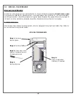
Page 30: ...r basis Replace flue pipes if there is any sign of corrosion or other problems Gaskets should be checked and may have to be replace BLOWER REMOVAL This furnace has a blower sealing system which is des...

Page 31: ...fied service technician service your oil filter or strainer Your service technician has the knowledge and equipment to properly perform this maintenance To ensure proper operation of this appliance oi...

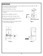
Page 32: ...il and power to furnace 2 Remove the two 2 screws securing the blower door Figure 1 3 Open blower compartment Figure 1 4 Disconnect the wiring to the blower motor 5 Remove the screw securing the blowe...

Page 33: ...WH BL BK BR RIELLO PRIMARY CONTROL YL BL TO TW TO TR WH BK BR BR CAP WH BK GND YL BL MOTOR 1 2 4 3 5 3 UNUSED 1 2 EAC CONT COOL HEAT 6 7 HUM X C F TRANSFORMER MHI 3 1 2 4 H C L ML N WH BK BL YL YL WH...

Page 34: ...VALVE VIOLET MOTOR ORANGE LIMIT RED L1 BLACK L2 WHITE CAD CELL WH WH WH TR TW GR BK GND BR BR CAP WH BK GND YL BL MOTOR 1 2 4 3 5 3 UNUSED 1 2 EAC CONT COOL HEAT 6 7 HUM X C F TRANSFORMER MHI 3 1 2 4...

Page 35: ...IGNITION BK GR VI L2 L2 L2 BK WH GND BR BR CAP WH BK GND YL BL MOTOR 1 2 4 3 5 3 UNUSED 1 2 EAC CONT COOL HEAT 6 7 HUM X C F TRANSFORMER MHI 3 1 2 4 H C L ML N WH BK BL YL YL WH BK BK 1 2 4 3 VI WH R...

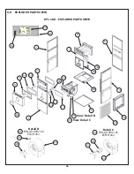
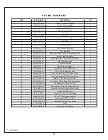
Page 36: ...W HTL 100 EXPLODED PARTS VIEW 3 5 1 4 28 29 30 6 2 9 18 8 7 15 11 12 13 19 20 21 22 Detail B FAN A0 0002 00 PSC Motor Detail C FAN A0 0002 01 ECM Motor 16 View Detail B View Detail C 23 23 24 25 27 26...

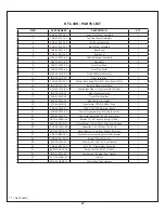
Page 37: ...n 1 17 ELB P1 0014 00 Cover Electrical Box 1 18 ELB A1 9001 00 Electrical Box Assembly 1 19 4TF 00 40VA 00 Transformer HTC 01A0BB01 40va 1 20 4CB 00 FAN0 01 1158 120 UTEC Electrical Board 1 21 FAN A0...

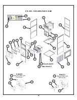
Page 38: ...PLODED PARTS VIEW 3 5 1 4 28 29 30 6 2 9 18 8 7 15 11 12 13 19 21 22 Detail B FAN A0 0004 00 PSC Motor Detail C FAN A0 0004 01 ECM Motor 16 View Detail B View Detail C 23 23 24 25 27 26 10 14 17 21 22...

Page 39: ...tion 1 17 ELB P0 0014 00 Cover Electrical Box 1 18 ELB A1 9001 00 Electrical Box Assembly 1 19 4TF 00 40VA 00 Transformer HTC 01A0BB01 40va 1 20 4CB 00 FAN0 01 1158 120 UTEC Electrical Board 1 21 FAN...

Page 40: ...ir band Combustion Results Chimney draft Ambient temperature Gross flue temperature Temperature rise External total static pressure A C Coil total resistance CO2 W C F F F see page 22 W C see page 22...

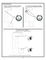
Page 41: ...atic Pressure Reading Supply Pressure Ps Return Pressure Pr A C Coil Total Resistance Reading Coil Pressure Pc Supply Pressure Ps Temperature Rise Reading Supply Temp Ts Return Temp Tr Probe must not...

Page 42: ...42 Page Left Intentionally Blank...

Page 43: ...43 Page Left Intentionally Blank...

Page 44: ...el 800 325 5479 www ecrinternational com USA Contact Canada Contact Granby Industries L P Industries Granby S E C 98 des Industries Cowansville Qc J2K 0A1 Canada 450 378 2334 www granbyindustries com...

Reviews: