16
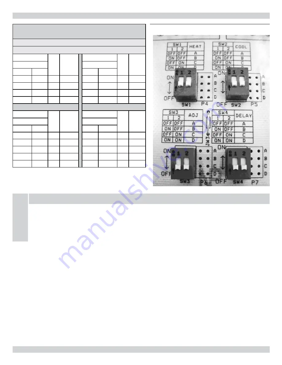
Table 8A - ecM blower set-up (hTlV-D)
100-10DD blower with ½ hP ecM
DIP SWITCH ADJUSTMENT CHART
FOR INPUT 0.75 USGPH TO 1.00 USGPH
SW1 - HEAT
POS. INPUT
USGPH
SW2 - COOL
POS.
AC
SIZE
(TON)
DIP Switch Position
DIP Switch Position
1
2
1
2
OFF
OFF
A
1.00
OFF
OFF
A
3
ON
OFF
B
1.10
ON
OFF
B
4
OFF
ON
C
1.20
OFF
ON
C
5
ON
ON
D
0.85
ON
ON
D
2
SW3- ADJUST
POS.
CFM
SW4- DELAY
POS. INPUT
USGPH
DIP Switch Position
DIP Switch Position
1
2
1
2
OFF
OFF
A
0%
OFF
OFF
A
1.00
ON
OFF
B
(+) 15%
ON
OFF
B
1.10
OFF
ON
C
(-) 15%
OFF
ON
C
1.20
ON
ON
D
N/A
ON
ON
D
0.85
ecM blOWeR (hTlV-D)
NOTICE
SW1 (HEAT) AND SW4 (DELAY) DIP SWITCHES MUST BOTH BE ADJUSTED ACCORDING TO INPUT (NOZZLE SIZE).
SW2 (COOL): 1 TON is approximately equal to 400 CFM
SW3 (ADJUST): (Heating Mode) Increase OR decrease temperature rise respectively
(Cooling Mode) Increase OR decrease CFM respectively
figure 4 - ecM blower set-up (hTlV-D)
Summary of Contents for HTL-100D
Page 18: ...18 Wiring Diagrams Figure 6 Chimney Vent Burner Wiring Diagram HTL D HTLV D...
Page 22: ...22 Oil Primary Control Sequence of Operation...
Page 31: ...31 Homeowner s Reference Table...
Page 33: ...33 PARTS LISTING HIGHBOY MODEL HTL D AND HTLV D Figure 9 Model HTL D and HTLV D...
Page 34: ...34 HTL D HTLV D Oil Fired Warm Air Furnace NOTES...


