61
User Interface Display
Explanation
Settings
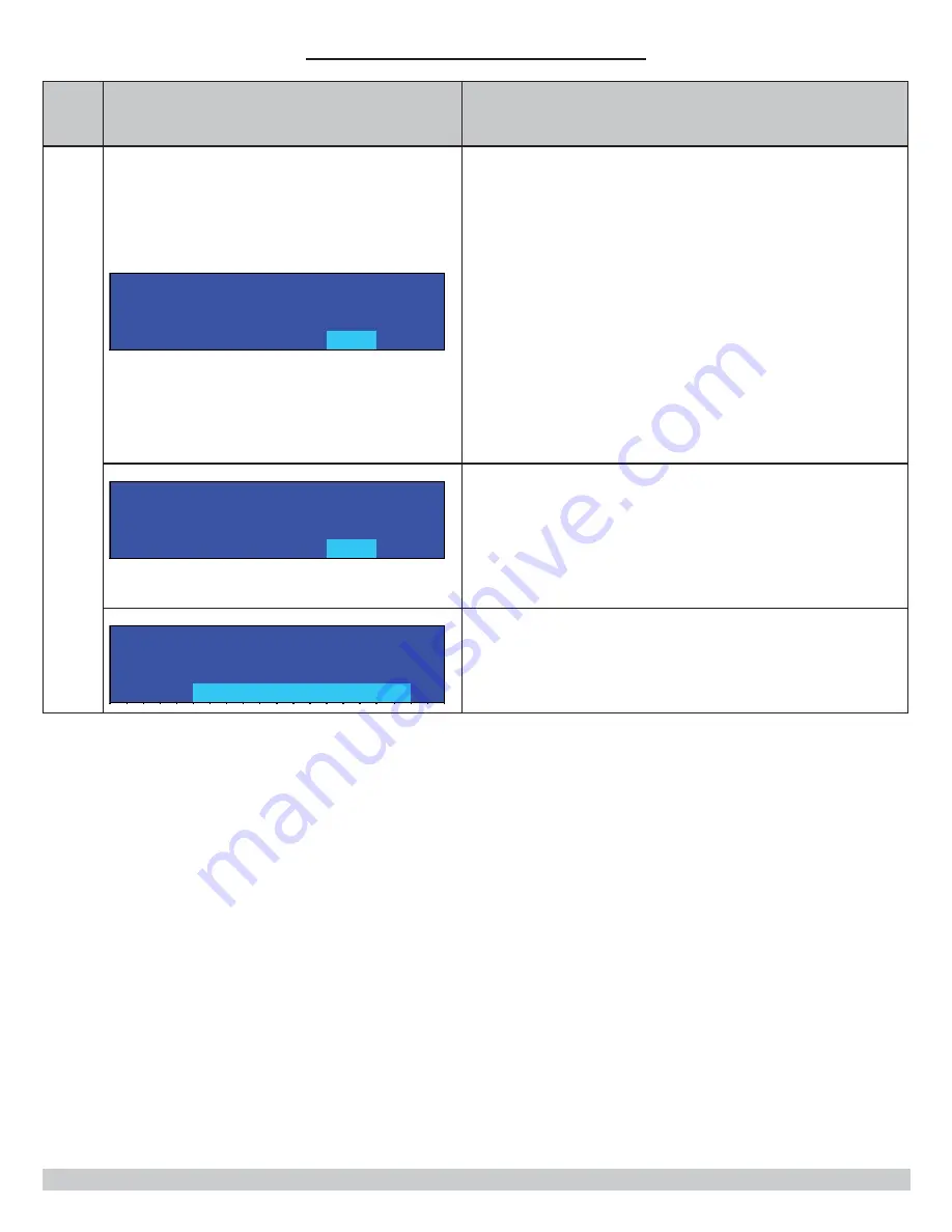
S E T T I N G S
C e n t r a l
H e a t
i n g
S e t p o i n t
° F
▼
Setting Range: 104° F to 195° F (40° C to 91° C)
Default Value: 140° F (60° C)
Adjust CH set point to hydronic system design while in
Operating in CH Mode = 0 (CH with Thermostat) or 3
(Permanent Demand).
In CH Mode = 1 (CH with Thermostat and Outdoor Reset) or 2
(CH with Full Outdoor Reset). Display will change to ‘OD Reset
Setpoint’ and cannot be changed. Controller calculates set point
based on outdoor temperature.
Note: For explanation of available CH heating modes, refer to
‘CH Mode’ section located in ‘CH Settings’ submenu.
S E T T I N G S
▲
D H W S e t p o i n t
° F
▼
Setting Range: 104° F to 195° F (40° C to 91° C)
Default Value: 180° F (82° C)
DHW set point determines supply water temperature set point
while operating in DHW mode.
S E T T I N G S
▲
C h a n g e
T e m p e r a t u r e
U n i
t s
F a h r e n h e i
t
° F
▼
User interface temperature unit of measure is selected using
‘Change Temperature Units’ screen.
Fahrenheit and Celsius available.
APPENDIX A - CONTROL MODULE
Summary of Contents for OLSSC-075
Page 45: ...45 13 TROUBLE SHOOTING...
Page 52: ...52 14 WIRING DIAGRAM 14 1 Connection Diagram...
Page 53: ...53 14 WIRING DIAGRAM 14 2 Schematic Diagram of Ladder Form...
Page 70: ...70 NOTES...
Page 71: ...71 Date Service Performed Company Name Tech Initials Company Address Phone...
Page 72: ...ECR International Inc 2201 Dwyer Avenue Utica NY 13504 4729 web site www ecrinternational com...


