background image

1. 

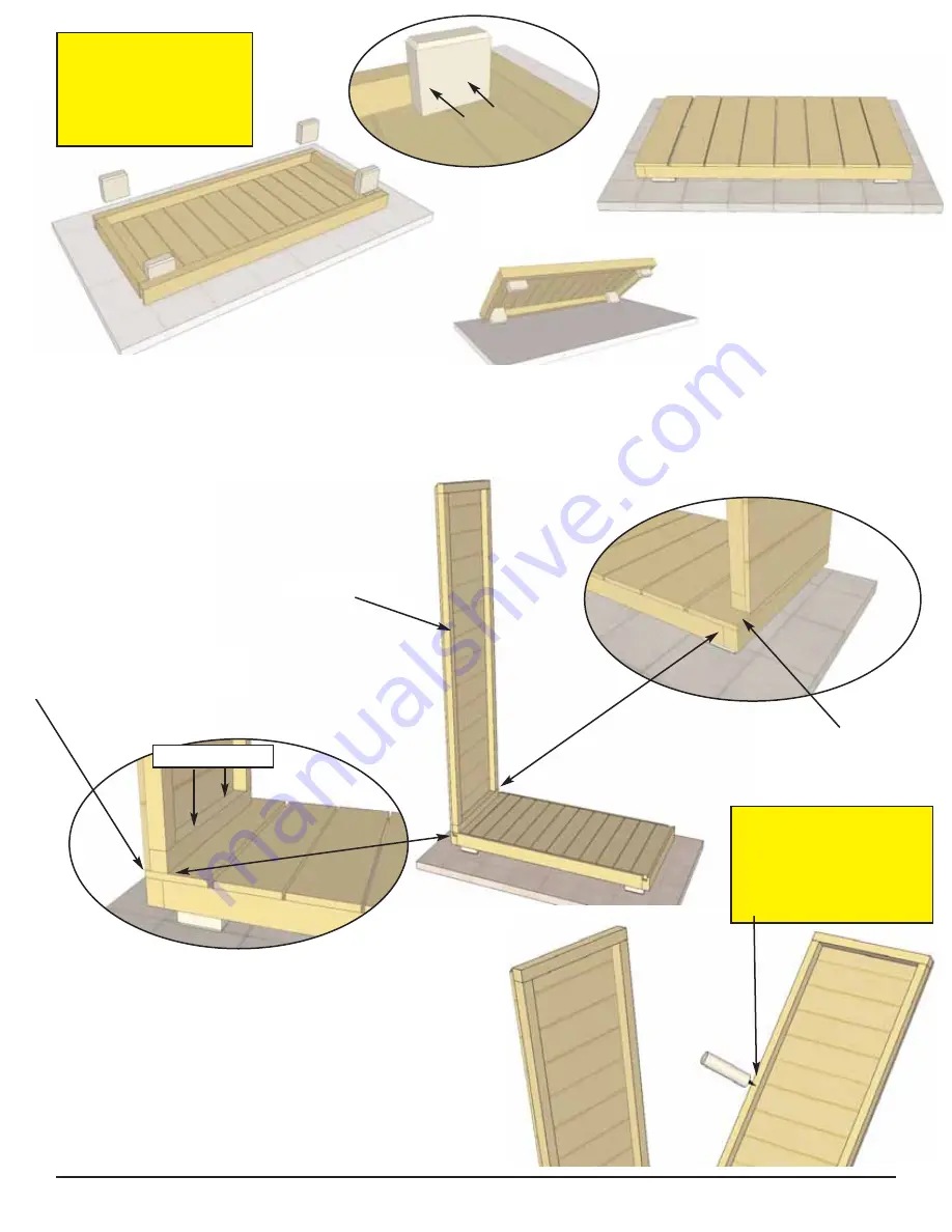
Flip 

Floor (A)

over on a level surface. Locate 

Legs (B)

and position in each corner tight to floor and 

framing and attach with 2- 2 1/2” screws. Complete all Leg att achments. Flip Floor over and complete Leg 

attachments by screwing 1 - 2 1/2” screws through Floor Boards into each Leg. Level Floor before 

proceeding to 

Step 2

.  

You can find the Square Drive Bit for the screws in with the Hardware Kit Bag.

Front

2. 

Locate 

Side Walls (C)

and 

Rear Walls (D)

. Make sure

walls are in correct orientation (Siding cut flush with Wall

Framing at bottom). Position Side Wall on Floor so it sits

flush with front and side. Have helper hold Side W all while

Rear Wall is positioned on Floor.  Screw Side Wall down

to floor with 2 - 2 1/2” screws when aligned correctly .

Optional -

Caulking wall seams will help prevent moisture

from entering at seam. 

Caulking not Included in Kit.

Front

Rear

Side Wall (C)

Side Wall Flush with Floor

Frame at Front and Side

At Rear, a gap

will exist. 

Caulking

Optional 

- Caulking

seams will help prevent

moisture from entering

at seam. 

Caulking not

included in kit.

Toll Free 1-888-658-1658                     sales@out doorlivingtoday.com

Page 4

You can find the
Square Drive Bit for
the screws in with
the Hardware Kit
Bag.

2 1/2” Screws

Summary of Contents for Garden Chalet 4x2

Page 1: ...ng code requirements are solely the customer s responsibility and should be abided by In high or gusty wind conditions it is advisable to keep the structure securely grounded Have a regular maintenance plan to ensure screws doors roof and parts are tight Garden Chalet 4X2 Assembly Manual Page 1 Revision 9 Oct 21th 2012 In the event of a missing or broken piece simply call the Outdoor Living Today ...

Page 2: ...lack Barrel Bolt Miscellaneous Not Shown on Illustration above 1 Barrel Bolt Plywood S pacer 1 2 x 2 1 2 x 2 1 2 1 Interior Silver Barrel Bolt X Floor Section A 1 Floor Section 20 1 2 x 45 x 2 1 2 B 4 Floor Legs 1 1 2 x 3 1 2 x 4 Wall Section C 2 Side W alls 18 1 2 x 62 1 2 D 2 Rear W alls 22 x 67 E 1 Door Header 1 1 2 x 2 1 2 x 41 Dado Cut G 2 Angle Cut Gable Siding Pieces left right 1 2 x 18 1 2...

Page 3: ...Square Drive Bit Hardware Kit Provided Safety Glasses Work Gloves Safety Equipment Required Not Provided Ladder Screw Gun Drill Tape Measure Hammer Wood Clamp Level Pliers Tools Required Not Provided Silver Barrel Bolt Toll Free 1 888 658 1658 sales out doorlivingtoday com DD Barrel Bolt 1 Utility Knife Page 3 1 8 3 8 Drill Bits 1 1 2 Bolt with Black Head Silver Nut and W asher ...

Page 4: ...ith Wall Framing at bottom Position Side Wall on Floor so it sits flush with front and side Have helper hold Side W all while Rear Wall is positioned on Floor Screw Side Wall down to floor with 2 2 1 2 screws when aligned correctly Optional Caulking wall seams will help prevent moisture from entering at seam Caulking not Included in Kit Front Rear Side Wall C Side Wall Flush with Floor Frame at Fr...

Page 5: ...osition 2nd Rear Wall Panel on Floor as per Step 3 4 Attach wall frames together at top middle and bottom with 3 2 1 2 screws Screw 2nd Rear W all down to floor with 2 2 1 2 screws when aligned correctly Side Wall Rear Wall 3 Align Rear Wall flush to floor at the back and wall framing of Side and Rear Walls together Rear Wall Siding Flush with Floor at back Wall Framing aligned together approx 1 2...

Page 6: ...l Panel correctly aligned attach Rear and Side Wall together at top middle and bottom of vertical wall frames with 3 2 1 2 screws 8 Screw right Side Wall Panel to floor with 2 2 1 2 screws when wall correctly aligned to floor Optional Caulking seams will help prevent moisture from entering at seam Caulking not included in kit Caulking ...

Page 7: ... your helper hold Header and Wall steady Secure with 2 2 1 2 screws per side You will want Front Corner Trim P to cover screws in Step 24 Use Trim to confirm screw location 11 Lay Roof Panel F on flat level ground Note overhanging Out side Shingles have been removed to avoid shipping damage and will need to be inst alled now Locate U V W Shingles There are 4 5 wide x 16 long U Shingles 2 6 wide x ...

Page 8: ...cure with 3 7 8 Shingle nails at least 9 from Butt Place and att ach a second U Shingle 5 wide in line with 2nd row of shingles Secure with 3 7 8 Shingle nails at least 9 from Butt Thick End 5 wide 6 wide V Thick End U 5 wide Secure with 3 7 8 Shingle Nails 2nd Row Shingle W 6 wide 24 To finish side place and attach W Shingle 6 wide x 8 5 long in line with 3rd and final row of shingles Shingle W w...

Page 9: ...oof evenly from side to side as illustrated above Recessed 1 8 back from Header Header Toll Free 1 888 658 1658 sales out doorlivingtoday com Page 9 11 From inside secure Roof to Wall Framing and Door Header with 7 2 1 2 screws Screw on angle to make sure screws don t penetrate completely through shingle roof p anel Angle 2 1 2 screws from Header and Wall Framing into Plywood Roof Sheathing ...

Page 10: ...sidings fit together Left Side Angle Cut Gable Siding G Roof and Angle Cut Gable Siding close together Gable and Wall Siding evenly aligned at rear 14 Complete right side Angle Cut Gable Siding Piece as per Step 12 13 Gable and Wall Siding evenly aligned at rear 13 When correctly aligned nail Angle Cut Gable Siding with 4 1 1 2 finishing nails Try to nail into the framing of Side Wall ...

Page 11: ... sales out doorlivingtoday com Page 11 Side Wall Frame 16 Locate Black T Hinges I Attach Hinges to Horizontal Door Trim using 1 1 1 2 Bolt with Black Head Note Door is Pre drilled for Bolt Tighten 10 Silver Bolt using wrench Finish Hinge by securing with 2 3 4 Black Screws Drill small pilot holes first to prevent wood from splitting Complete both Doors 4 Hinges Starting with left side Door lift un...

Page 12: ...gle 1 8 gap 1 8 gap Gap between Top of Door and Door Header 19 Position Right Side Door as per Steps 16 17 Once again use only 1 screw per hinge initially to secure Door to Vertical Door Frame Trim Open and close both Doors to confirm proper Door closing Re adjust Door Screws if necessary When satisfied complete Hinge attachments with 2 additional 2 Black Screws per Hinge 1 2 Black Screw initially...

Page 13: ...arting with the side position tight to Corner Door Trim and flush with bottom of Floor Secure with 3 1 1 4 Nails per piece Complete other side Position Rear Skirting Piece between Side Skirting and secure with 6 1 1 4 nails Toll Free 1 888 658 1658 sales out doorlivingtoday com Page 13 23 Filler Trims O or nailing strips are positioned in rear side corners There are 2 Fillers per rear corner Start...

Page 14: ...s Side Front Corner Trim P 25 Locate Side Rear Corner Trims Q and Rear Corner Trims R Position 1 each in rear corner as illustrated above At bottom Trims should sit flush with Side and Rear Skirting When correctly aligned secure each piece with 8 1 1 2 nails Toll Free 1 888 658 1658 sales out doorlivingtoday com Page 14 Side Rear Corner Trim Q R 21 Position Upper Rear Horizontal Trims L underneath...

Page 15: ...e Ridge Cap slightly off the back of the shingles Secure with 4 2 1 2 screws Be sure to screw through the Ridge Cap and into Rear Wall framing Drill pilot holes in Ridge Cap to prevent wood from splitting 37 Shelving may be mounted on Left or Right Side of Chalet This Assembly Manual illustrates the Shelving being mounted on the Left Side First locate the Vertical Shelf Support Y Measure 19 from L...

Page 16: ...n each end Note Make sure Shelf Support is level prior to att aching Attach 2nd Shelf Support to Side Wall framing as described above Place Shelf AA on top of Shelf Supports Shelf Support Z Positioned 3 4 on Side Wall framing Drill pilot hole on angle before screwing 39 Secure Shelf to Shelf Supports with 4 1 1 4 screws Drill pilot holes to prevent wood from splitting 40 Complete positioning and a...

Page 17: ...d in Hardware Package to attach Tap barrel of bolt with Hammer to mark location on Header Open Door and Drill with a 3 8 bit Right Door 43 Attach Door Handles CC Handles are positioned on top section of each door and mounted with 3 4 Black Screws Attach Black Barrel Bolt DD as illustrated above with 3 4 Black Screws Note how female part of Barrel Bolt is positioned higher than male Do a dry run fi...

Page 18: ...eedback and would like to hear back from you on how well we are doing in the following areas 1 Customer Service 2 On Time Shipping 3 Motor Freight Delivery 4 Quality of Materials 5 Assembly Manual 6 Overall Satisfaction Please call write or email us at The materials contained in this Assembly Manual may be downloaded or copied provided that ALL copies retain the copyright and any other proprietary...

Reviews: