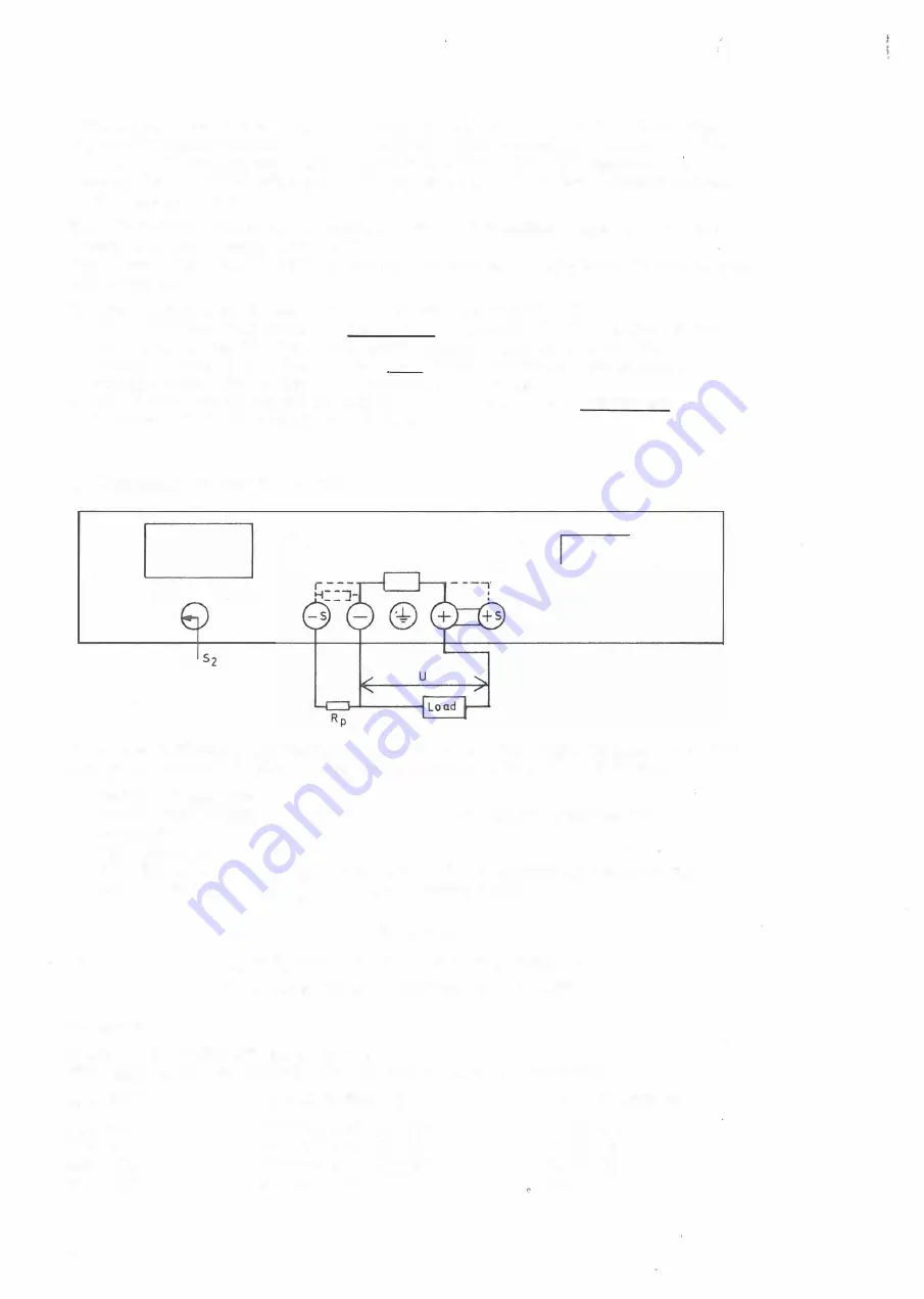
This circuit permits sensing the voltage at the load terminals instead of at
the power supply terminals. Thus regulation loss caused by
IR
drops in the
load leads is compensated for. The influence from the resistance in the
''sens e" leads is negligible as a low (a few mA) and almost constant current
flows through these.
Set "EXT-INT" switch S2 in position "EXT" . If possible, connect cable with
lowest expected voltage drop to "+" .
When using the remote sensing circuit, the following limitations should b e taken
into account:
1 . The voltage drop in the "+" cable should not exceed 0, 5 V.
2 . The maximum voltage at the instrument terminals should not exceed the
maximum rating for the actual power supply. This means that the
maximum available voltage at the load is the maximum power supply
voltage minus the voltage drop in the power cables .
3 . The power supply voltmeter indicates the voltage at the instrument
terminals (not the voltage at the load) .
E . RESIS TANCE PROGRAMMING
D
0
0
EXT
Figure 4
0
0
�'o
When the resistance programming mode is used, the output voltage is control
led by an external resistor. The connection procedure is as follows�
1 . Switch off the power
2 . Set "sense" switch S2 to "EXT" and connect jumper between "+" and
"+sense".
3 . Set voltage control at zero.
4. Now the output voltage is controlled by the programming resistor RP .
The relation between RP and output voltage U is :
where :
Exception:
U
=
K . R (R in kohms)
p
p
p
K
=
3, 75 for 32 V models (270 ohms/V)
p
K
=
3, 35 for 60 V models (300 ohms/V)
p
E arly 60 V RAC PAC 'S have Kp
=
3, 75
This applies for RAC PAC'S with the following serial numbers :
MODE L
SWEDISH SER. NO
DUTCH SER. NO
B6 0-2 , 5R
B6 0-5R
B60- 10R
B60- 15R
1 0
0 0 1-004 and 100- 125
0 0 1-004 and 100- 140
0 0 1-003 and 100- 125
001-110 and 100- 110
Nl00- 1 2 1
Nl00- 1 2 1
Nl00- 106
Nl00- 106


