Page 16 from 22
921316000_09_016
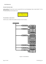
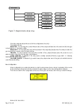
SETUP ZONE
RELAY ON ALARM1
RELAY ON ALARM2
RELAY ON ALARM3
RELAY ON FAULT
SAVE ZONE
1..17
1..17
1..17
1..17
1..17
Figure 12: Diagram menu of the zone configuration
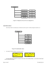
Information menu
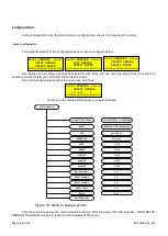
From this selection the technician can be informed for all the system. The below diagram shows the menu
INFORMATION
SENSORS
ZONES
BATTERY
MAINS SUPPLY
VCC VOLTAGE
RELAY
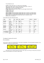
An example of the information of a sensor screen are
The above left screen shows the number of the sensor, the condition (FAULT -), the current consumption
and the name of the sensor.
Figure 8: Information menu
4:Z=0 R=20 (+)
A1= 7 A2= 10 A3= 20
O1= 1 O2= 2 O3 = 3
OF= 4 ZONE = 0
4: FAULT -
I = 2.0 mA
LPG FLOOR 1
====================

