Page
2 of
5
921477000_0
9
_00
5
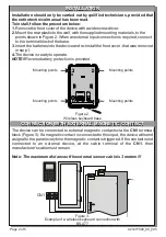
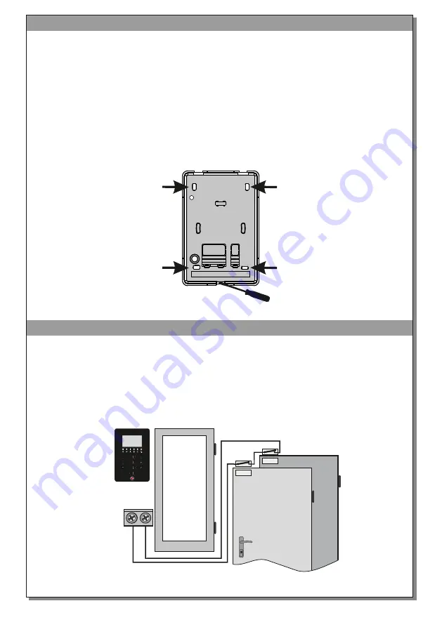
The device can be connected to external magnetic contacts via the
CN
1
terminal
block
(Figure 3). If a magnetic
contact
is connected to this input, the device
will
send
a
signal
to the panel
everytime the magnetic contact is triggered
.
If
the contact is not
connected to an external device, at the
cable
terminal
of the
CN
1
, the
n
manufacturer
’s cable
must remain.
Note:
The maximum distance of the external sensor cable is 3 meters !!!
Installation should only be carried out by
quili
fied technicians, provided that
the entire technical manual has been read.
To install, follow the procedure below:
1.
Remove the
front cover
of the device with a wide screwdriver.
2.
Mount the rear plastic to the wall, with the supplied mounting materials,
to
the
points shown in Figure 2. When an external input connection is required
,
connect
to
the terminal block
of
the base.
3.
Insert the batteries into the device and re
-install
the f
ront cover
, that was removed
in step
1.
4.
The device is ready to operate.
NOTE!!
Reverse battery protection is provided
.
INSTALLATION
INSTALLATION
CONNECTION WITH EXTERNAL MAGNETIC
CONTACT
CONNECTION WITH EXTERNAL MAGNETIC
CONTACT
CN
1
Figure 3.
Example of a wireless keyboard connection
with
BS-477
Figure 2.
Wireless keyboard base
Mounting points
Mounting points
Mounting points
Mounting points


