921536000_23_010
Page 1 from 2
BS-536
manual call point
1293-CPD-0256 11
EN-54-11: 2001 + A1: 2005
KOLINDROS
PIERIAS
60061 HELLAS
1293
MANUAL CALL POINT
TECHNICAL CHARACTERISTICS
OPERATION TEMPERATURE RANGE
RELATIVE HUMIDITY
EXTERNAL DIMENSIONS
CONSTRUCTION MATERIALS
TYPICAL WEIGHT
GUARANTEE
OPERATION VOLTAGE
ALARM CURRENT
ALARM RESISTOR
TYPE
USE
DEGREES OF COVER PROTECTION
PRODUCED IN ACCORDANCE WITH
Type A
Indoor
10-30V DC
470ohms
8-30mA
Bayblend FR3010
IP 20
EN 54-11
-10 to 70 C
o
Up to 95%
2 years
98 x 94 x 58 mm
180gr.
BS-536
High Quality European based Manufacturers
Thank you for purchasing this product of Olympia Electronics. A
European manufacturer.
GENERAL
This is an emergency fire alarm button. Use this call point to
manually activate the alarm system at the sight of fire. It is
essential for it to exist in cooperation with other detectors.
Using it is very simple. All you have to do is push the see-through
plastic cover and the call point automatically activates the alarm
system.
In this case the see-through plastic cover does not brake but it
can be reset to it`s original position with the special plastic key
which is included.
This way you can test a specific call point and maintenance the
fire detection panel as well.
It is used as a signal to evacuate the building in case of fire.
In every fire detection system it is essential that you place one
call point besides the control panel and the rest mainly in
corridors and exits of the building.
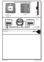
Installation and Connection
1.
First, unfasten the retailing screws and remove the plastic
cover.
2.
Remove carefully the interior parts of the device and use the
supplied mounting parts to the A-A or B - B positions (Figure 2).
3.
During their installation must be attention taken that the distance
between two buttons does not exceed 30 m and all buttons
should be placed at a height of about 1.4 m from the floor.(Figure
1).
4.
Inside the call point there are four special terminal blocks
with indications IN and OUT used to fasten the cables.
The connection is made direct to the zone of the control
panel regardless of polarity. If in a zone there are more than
one then they are connected in parallel. If in the same zone
there are detectors then the call point is connected in
parallel with the detectors of this specific zone.
If the last device installed on a zone is a call point then
you must place on it the resistor which was removed from
that zone. The Figure 4 below shows the connections
between two call points and a detector to a zone of a fire
detection panel It also shows the connection of the resistor
to the last button of that zone.
5.
Reinstall the parts which have been removed during the
previous steps and the device is ready to operate.
Certification
The manual call point BS-536 is certified from EVPU and
LPCB (1010c/01). Also EVPU controls the production under
CPD number :


