Page
3 from
5
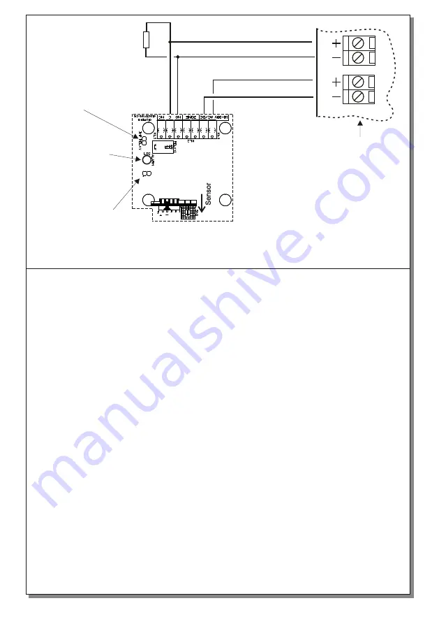
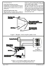
Figure 3.
Connection diagram of a detector with a fire panel of other company.
Ζ
o
n
e
1
0
-3
0
V
D
C
Terminal Resistor
LED Alarm
Jumper for programming
alarm latch mode
Fire panel
Relay resistance
selection jumper
Sensitivity
The BS-685 detectors are activated when the
content of gas (propane), in the monitored area,
exceeds 5 - 15% of the lower explosive level
(L.E.L).
The BS-686 detectors are activated when the
content of gas (methane), in the monitored area,
exceeds 5 - 15% of the lower explosive level
(L.E.L).
The devices are connected to 24_M, of a gas
panel, as shown in figure 2. When a detector is
activated, it gives an alarm signal to the gas
panel. The activation stops when:
A) You push the test button or when you cycle the
power of the detector (Alarm latch mode) (figure
4).
B) You push the test button or the gas content
drops below 5-15% of the L.E.L. (Νο alarm latch
mode) (figure 5).
Indication LEDS and Operation
When first installed, you must wait 20 seconds
until the sensor compensates to its surroundings.
When the red LED is lit then the unit is in alarm
mode. Alarm mode can be triggered from the
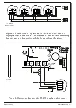
sensor of the unit. Figure 4 shows a connection
diagram between 4 BS-685 or BS-686 and a gas
panel.
Waterproofing of the device
The package contains a sealing gasket which is
installed on the rim of the front cover in order to
water-proof the unit.
Relay resistance Selection (JMP RELAY)
There is the capability to select the alarm relays
resistance, with the use of the resistance
selection Jumper. When a link is used on the
jumper, then the used resistance is zero, and an
external resistence may be used. If there is no
link, then the on board resistence of 440 Ohm is
used.
ATTENTION!! The devices must not be
tested using gas filled lighters because the
sensor will be destroyed.
921686000_09_01
7


