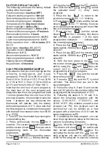
Page
12 from
1
4
Installation procedure
Installation procedure
Fig
. 1
Fig
. 2
Fig
. 3
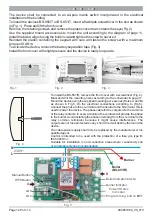
Install the front cover with slight pressure and the device is ready to operate
.
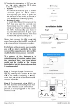
To activate the device, remove the battery separation tape
(
Fig
.
3).
Reinstall the plastic containing the keypad with care and fasten the screws with a maximum
torque of
0,
4
Nm.
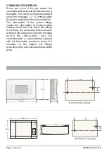
Use the supplied mount accessories to mount the unit according to the diagram of page 11.
Install the base, align it using the built in vial and tighten the screw to secure it.
Remove the retaining screws and remove the plastic cover that contains the keys (Fig
.
2).
The device shall be connected to an all-pole mains switch incorporated in the electrical
installation of the building
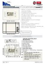
To install the devices BS-850/T or BS-851/T
,
insert a flat blade screwdriver in the slot as shown
in (Fig. 1). Press and lift the front cover.
Fig
. 4
To install the BS-851/R
,
remove the front cover
with a screwdriver
(
Fig
.
4).
Mark and drill the mounting holes according to the schematic in page 11.
Mount the device using the supplied mounting accessories (Holes A and B)
as shown in Fig.5. Do the electrical connections according to (Fig.5).
Connect the phase to the L terminal and the neutral to the N terminal, this is
used to power the device. The phase cable for the outputs is to the common
of the relay contacts. In every activation, the contacts will provide the phase
to the burner. Avoid installing the phase internally (from the L terminal to the
relay common terminals) because it might cause interferences. The
outputs are not fuse protected so any short circuit will destroy them and the
device.
The cable power supply shall only be replaced by the manufacturer or his
qualified agent.
Suitable for installation in non-conductive areas where conductivity can
occur temporarily due to condensation.
Control is intended to be used with the protection of a fuse gG, type B,
IEC60269-3-1.
N
L
230V~
Boiler Indicator
(BS-851)
LD5
LD4
Boiler
(BS-851/R)
Burner
Fig
. 5
Burner Indicator
A
B
WPS Button
Manual Button
Power/Status
Indicator
Programming button
BT1
940851000_09_010

