980190000_09_007
Page 2 of
3
degree.(Fig
.4)
While holding the external section
steady, rotate the internal section in order to add or
subtract the temperature difference that was
calculated.
After this is finished re-insert the knob on the
thermostat.
WARNING,
do not power the thermostat with the
mains power supply if the cover is not secured into
position.
1
2
3
Mounting
points
Fig
.2
Fig
.3
Fig
.4
61mm
61mm
60mm
2
0
e
s
a
er
c
nI
e
s
a
e
r
c
e
D
1
2
3
4
L
N
230V AC
K
ON-OFF
switch
Output
Activation
Indicator
Connection
terminals
Burner
or
Electrovalve
Internal
View
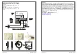
Figure 1. Connection diagram
WARRANTY
Olympia Electronics guarantees the quality, condition and operation of the goods. The period of
warranty is specified in the official catalogue of Olympia Electronics and also in the technical leaflet,
which accompanies each product. This warranty ceases to exist if the buyer does not follow the
technical instructions included in official documents given by Olympia Electronics or if the buyer
modifies the goods provided or has any repairs or re-setting done by a third party, unless Olympia
Electronics has fully agreed to them in writing.
Products that have been damaged can be returned
to the premises of our company for repair or replacement, as long as the warranty period is valid.
Olympia Electronics reserves the right to repair or to replace the returned goods and to or not
charge the buyer depending on the reason of defection. Olympia Electronics reserves the right to
charge or not the buyer the transportation cost.
HEAD OFFICE
72
nd
km
.
O
.
N
.
R
.
Thessaloniki-Katerini
P
.
C
. 60300
P.O.
Box 06
Ε
ginio Pierias
Greece
www.olympia-electronics.gr
info@olympia-electronics.gr
980190000_09_007
Page 3 of
3


