Date
27/06/2019
Document number
921100400_09_002
Page
41 of 67
41 / 67
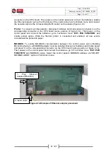
connector on the CPU board. Then power on the control panel and connect the batteries, enable
the Ethernet adaptor set up the IP address of the control panel via Technician menu and connect
the network cable to the corresponding RJ45 socket on the adaptor (figure 4-14).
-
Printer
: To connect a printer adaptor, disconnect batteries and mains power and place it on the
corresponding connector on the CPU board (same position of figure 4-14). Then power on the
control panel and connect the batteries
, go to Technician menu “
EXT. PCB FUNCTION
” and
enable printer option. While the thermal printer is connected and enabled, all new events
recorded will be printed on paper.
-
MODBUS
: To enable MODBUS communication between the control panel and a Building
Monitoring System, a MODBUS adaptor must be installed. Disconnect batteries and mains power
and place it on the corresponding connector on the CPU board (same position of figure 4-14).
Then power on the control panel and connect the batteries
, go to Technician menu “
EXT. PCB
FUNCTION
” and MODBUS option. Select the control panel’s MODBUS address via “SELECT
MODBUS ADDR.” option in Technician menu.
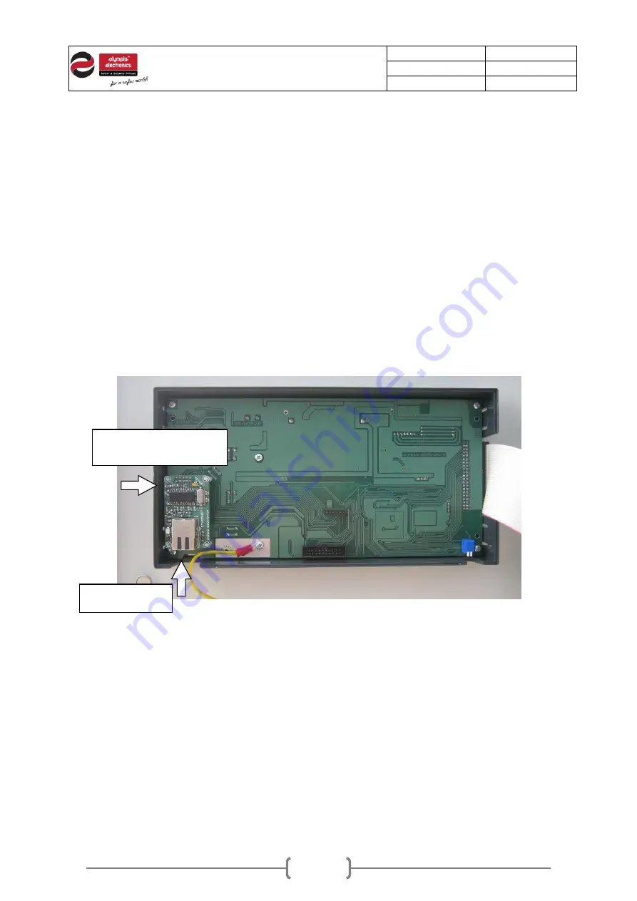
Figure4-14.Example of Ethernet adaptor placement
1.
Plug
Ethernet
adaptor (GR-8530)
2. Insert cable

