Date
27/06/2019
Document number
921100400_09_002
Page
52 of 67
52 / 67
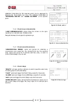
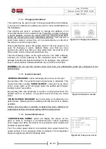
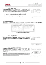
First option, “
PANEL ADDRESS
” will open an input window to
configure the control panel’s address within the network of panels.
Each address must be unique. Address number 1 is given to the
master control panel. Addresses 2, 3 and 4 are given to subpanels.
Figure5-27.Panel address
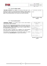
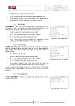
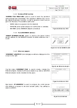
Second option, “
NETWORK SETUP
” is used to enable or disable
panel networking on a control panel. When set to enable, a master
panel enables data transmission via the RS-485 port and a subpanel
reads transmitted data via the same port.
Figure5-28.Network setup
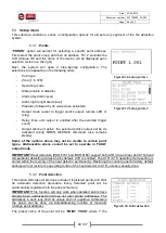
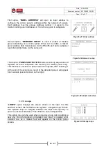
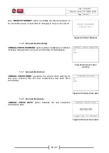
Third option, “
PANELS DETECTION
” starts a scanning sequence and
registers all found subpanels into memory (for master panel only).
This function is crucial for a panel network to operate, after enabling it.
At the end of the scanning a result of the detected panels will appear
for 2 seconds (second screen on the right).
Figures5-29.Panels detection
5.3.10
Loops
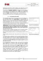
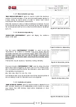
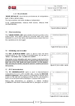
“
LOOPS
” option displays the screen shown on the right. Via this
selection screen, the technician can register / unregister loop circuits.
Use up/down keys to navigate between the loops and right key to
select or unselect activation. Press Enter to save configurations.
This option may only be used when removing a loop card or adding a
new one. Do not unregister an installed loop circuit or register a not
installed one, as a relative fault will appear on the control panel
screen.
Figure5-30.Setup loops

