Date
27/06/2019
Document number
921100400_09_002
Page
33 of 67
33 / 67
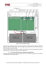
Figure 4-3.Mains power supply connection
Caution!
1. Any assignment of installation, repairs or electrical equipment maintenance must be executed with
both mains power supply and batteries disconnected.
2. Connect the batteries and enable mains power supply to the control panel only after all other cable
connections have been completed.
3. The mains power fuse of the panel is located in the power supply unit, rated 4A/250V (Fast), TR5
(non replaceable).
4. The battery protection fuse is self-restoring, 900mA rated soldered on the main board (non
replaceable).
4.2.4
Connecting the batteries
The interior of the control panel has a space appropriate to accommodate two 12V lead-acid batteries
(Pb) with the optional capacity of 7Ah, 9Ah, 12Ah or 15Ah. Both batteries must be of the same type and
capacity.
Use BATTERY CALCULATOR tool included in BSR-100X software application to
calculate the required battery capacity.
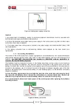
The batteries must be connected in series. In the battery area there are two wires, one red and one
black for connecting the batteries. The red wire must be connected to the positive pole of the first
battery; the black wire must be connected to the negative pole of the second battery. An extra cable is
included in the package; use it to connect the rest of the poles in between (negative pole of the first
battery to the positive pole of the second battery). On the following figure 4-4, the batteries connection
diagram is depicted.
In case of battery replacement, the new batteries must be of the same type and capacity.
Don’t
mix new with old batteries.
Don’t discard the old batteries in common waste bins. Discard old
batteries only in special bins for lead-acid battery waste, for collection and recycling.
It is recommended to disconnect mains power of the control panel while replacing the batteries
for safety reasons.
Figure4-4.Battery connection

