Date
27/06/2019
Document number
921100400_09_002
Page
38 of 67
38 / 67
4.4
Panel network connections
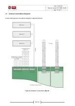
A network of panels can support up to
4 interconnected control panels
. Each control panel owns a
unique address. The master panel owns the address 1 and the subpanels have the addresses 2, 3 and
4.
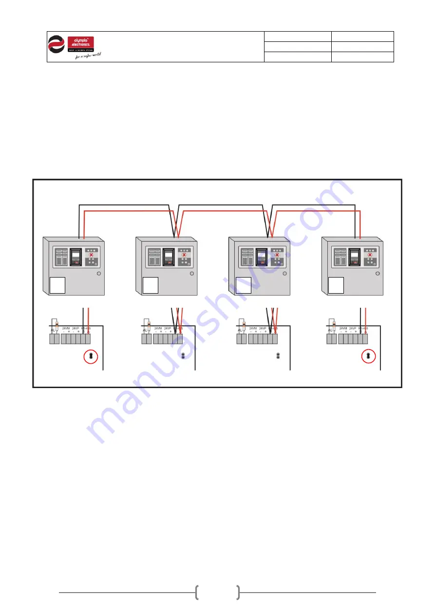
The interconnection wire must be twisted pair (2-core). The connection method must be in parallel,
meaning that the same wire goes along the panels without any splitting, just like in the following diagram.
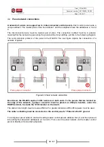
The communication protocol of the panel is the RS-485. The next figure depicts the connection of a
network of panels.
Figure4-11.Panel network connection
Be advised, the RS-485 requires 120
Ω resistors on both ends. To the panels that are located on
the edge of the network, a jumper connector must be placed on CN4 pin headers, under the
RS485 terminal, to enable the 120
Ω resistor on the board.
The
cable’s total length must not exceed 500m. For greater distances a RS-485 repeater must be used.
The cable
’s shielding must be connected on the control panel’s “Protective Earth” ground.
To configure a panel network, start with setting master control panel
’s address first (1) and then proceed
into setting the subpanels
’ addresses (2, 3 and 4). Then, scan the panel network via the master control
panel to identify all connected subpanels.
Place jumper connector
Place jumper connector
1
2
3
4


